
Interactive electronics resource
Light Alarm Kit Instructions
Build, understand and experiment with the Light Alarm Kit. This resource brings the original kit material into the current MitchElectronics format with the schematic, circuit explanation, component and PCB information, construction guidance, troubleshooting and practical ideas where available.
Introduction
The Light Alarm Kit, as the name suggests, lets you build a light-activated alarm. An onboard photodetector converts ambient light into electrical signals, and a comparator checks to see if the detected light is above a threshold. If so, an alarm circuit is triggered, alerting those nearby that light has been detected.
The detection circuitry uses a latch to remember the detection of light. By doing so, the buzzer will continue to beep even if the surroundings become dark again. A small reset switch on the board allows users to reset the beeper, thus rearming the device.
Schematic
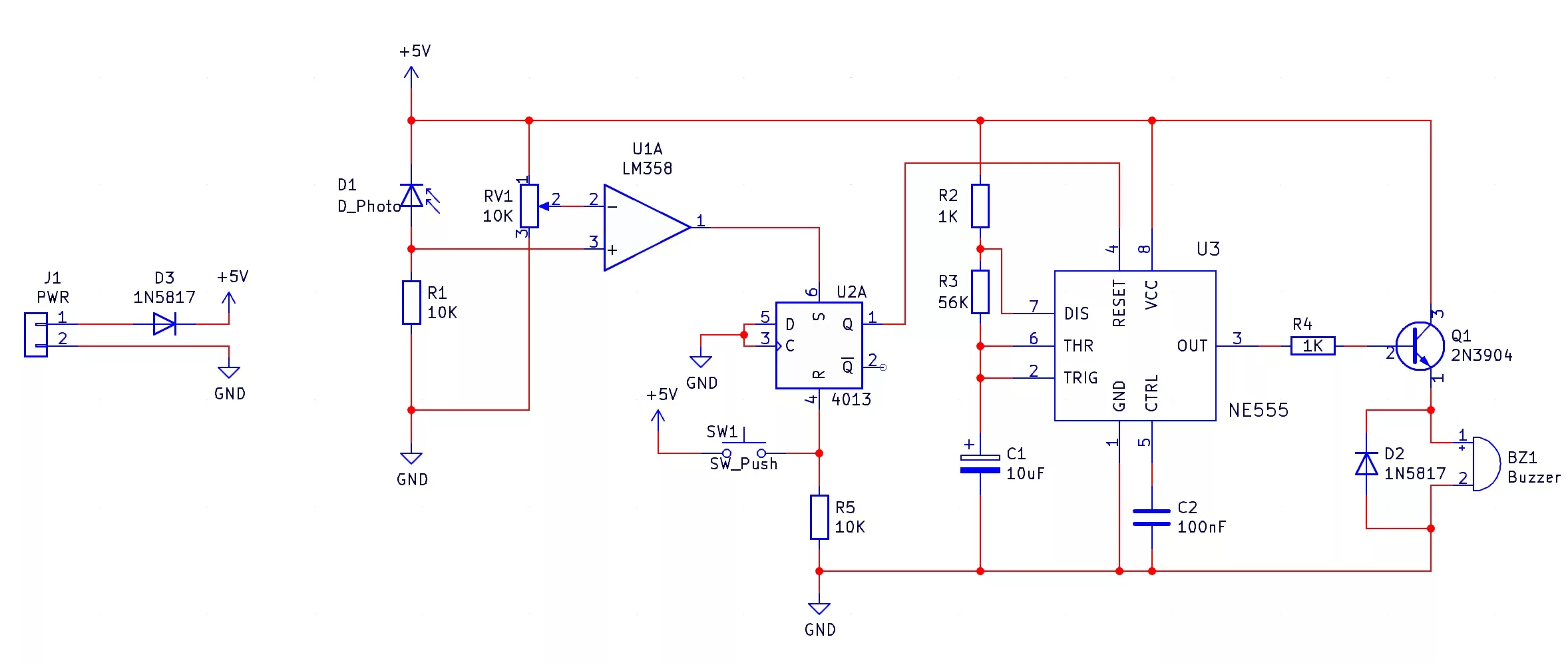
How does the light alarm work?
The Light Alarm is a circuit that sounds a buzzer when the light level falling on the circuit reaches a certain level. However, once triggered, the circuit will continue to beep even if the light falls below the trigger level, and this can be useful in security situations where a burglar’s torch activates the alarm! So, how does this circuit work and what makes it better than other light detection circuits?
The most important component in this kit is D1 which is a photodiode. Photodiodes are essentially sensitive LEDs that produce a current when light falls on them. In our circuit, you will notice that D1 is in reverse bias configuration, which means that when there is no light falling on D1, current cannot flow through D1, and therefore, the voltage across R1 is 0V. When light falls on D1 it causes D1 to become conductive and therefore conduct current, which causes a voltage to form across R1. This is the light detection stage and the voltage across R1 is then sent to the comparator stage.
The next stage is the comparator stage which is made up of a single op-amp U1 which compares the voltage across R1 with a potentiometer. The potentiometer is used to set the sensitivity of the light detector and when the voltage across R1 is greater than the voltage from the potentiometer then the out- put of the comparator goes to +5V. Since the output of the comparator is connected to the SET pin of the 4013, the 4013 latch U2A is set when the comparator detects a light level greater than the potentiometer setting. The output of U2A is connected to the RESET pin of the 555, which is an inverted input, so when the output of the 4013 is 0V the 555 stops oscillating and when the output of the 4013 is +5V then the 555 oscillates.
The 555 oscillator is connected to a transistor driver that provides power to the buzzer, which beeps whenever the transistor is turned on. When the 4013 is set, the 555 can oscillate, which causes the buzzer to make short beeps like a security alarm system and the magnetic buzzer in this kit can make a lot of noise! If the system is to be reset and armed, the button SW1 is pushed, which resets the latch U2A and therefore prevents the 555 astable from oscillating.
To summarise
- R1 produces a voltage across it when light falls on D1
- The comparator sets the latch U2A when the voltage across R1 is greater than RV1
- The latch controls the 555 astable circuit, and enables it when its output is high (Q = +5V)
- The 555 astable controls a transistor which provides power to a buzzer
Project ideas
Burglar Alarm
One of the best uses for this kit is as a burglar alarm. By placing this circuit near your valuables, anyone who attempts to burgle your valuables and accidentally shines light onto the kit will trigger the circuit, alerting you and others of the burglary in progress.

Headlight Warning System
When parking your car, it is easy to leave the headlights on, as many cars don’t warn drivers that they have been left on. If they are, it is possible to drain the battery, making it impossible to start the car later. As such, this circuit can be designed to turn on when the car is off, and detect the presence of light coming from the headlights to alert you that the lights are still on!

Darkroom Integrity Monitor
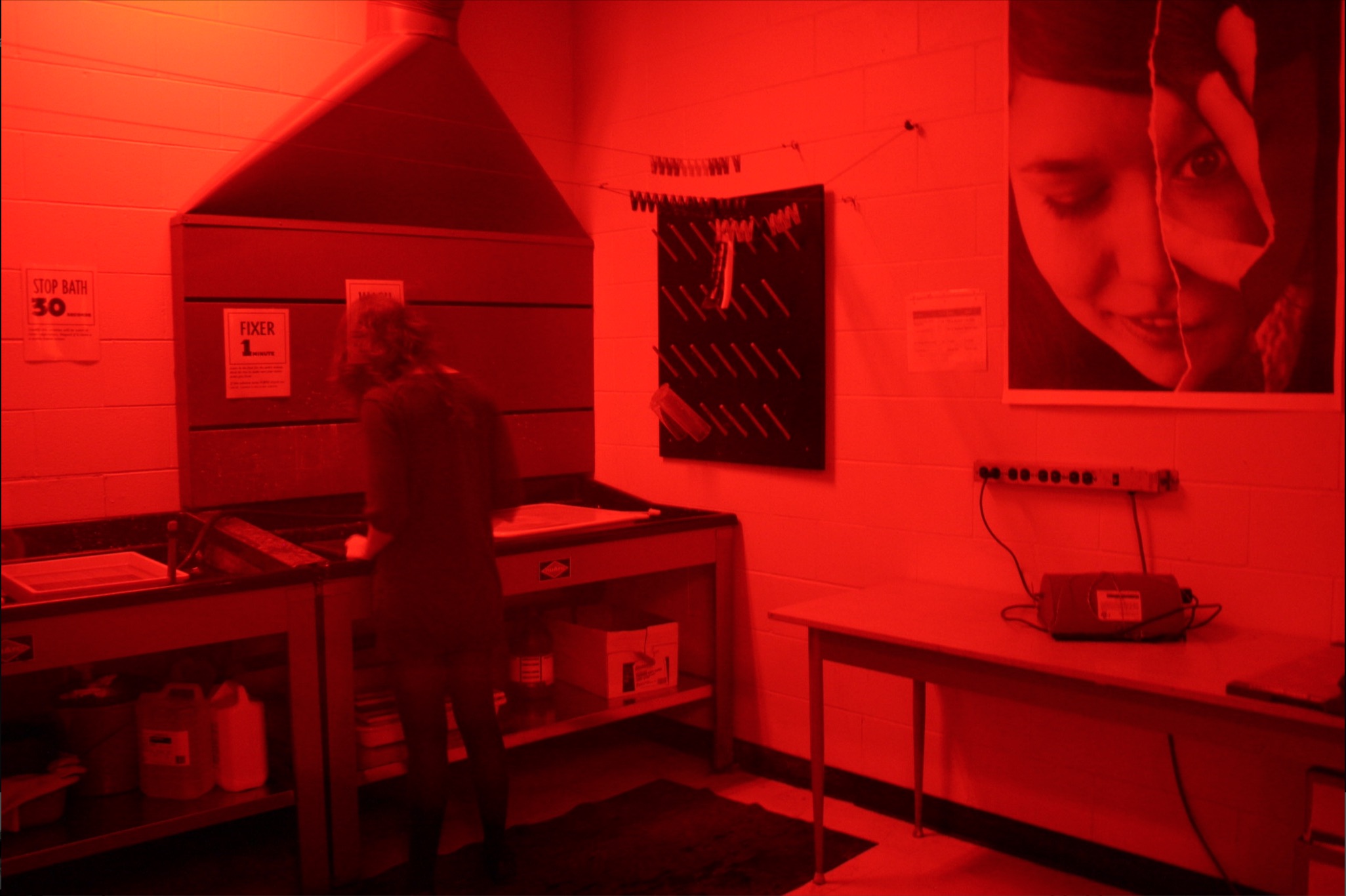
In photography, dark rooms are specially designed rooms for developing photographic film, and are called dark rooms as outside light must be kept out. If any light gets into the room, it risks overexposing any undeveloped film, and this will destroy images. The Light Activated Alarm can be designed to trigger on light levels going over a specified value, thus alerting nearby users that dangerous amounts of light is present.
Try it yourself
Circuit simulation
Not available in mobile view
What you need
Component List
| Component | Quantity | PCB Reference |
|---|---|---|
| 8 DIP Socket | 2 | U1, U3 |
| 14 DIP Socket | 1 | U2 |
| LM358 | 1 | U1 |
| NE555 | 1 | U3 |
| 4013 | 1 | U2 |
| 100nF Capacitor | 1 | C2 |
| 10uF Capacitor | 1 | C1 |
| 1KΩ Resistor | 2 | R2, R4 |
| 10KΩ Resistor | 2 | R1, R5 |
| 56KΩ Resistor | 1 | R3 |
| 10KΩ Potentiometer | 1 | RV1 |
| 1N5817 Diode | 2 | D2, D3 |
| 2N3904 | 1 | Q1 |
| Photodetector | 1 | D1 |
| Buzzer | 1 | BZ1 |
| Tactile Switch | 1 | SW1 |
| Black Wire | 1 | J1 |
| Red Wire | 1 | J1 |
| Light Alarm PCB | 1 | — |
Inspect the board
Interactive BOM
Board reference
PCB & assembly
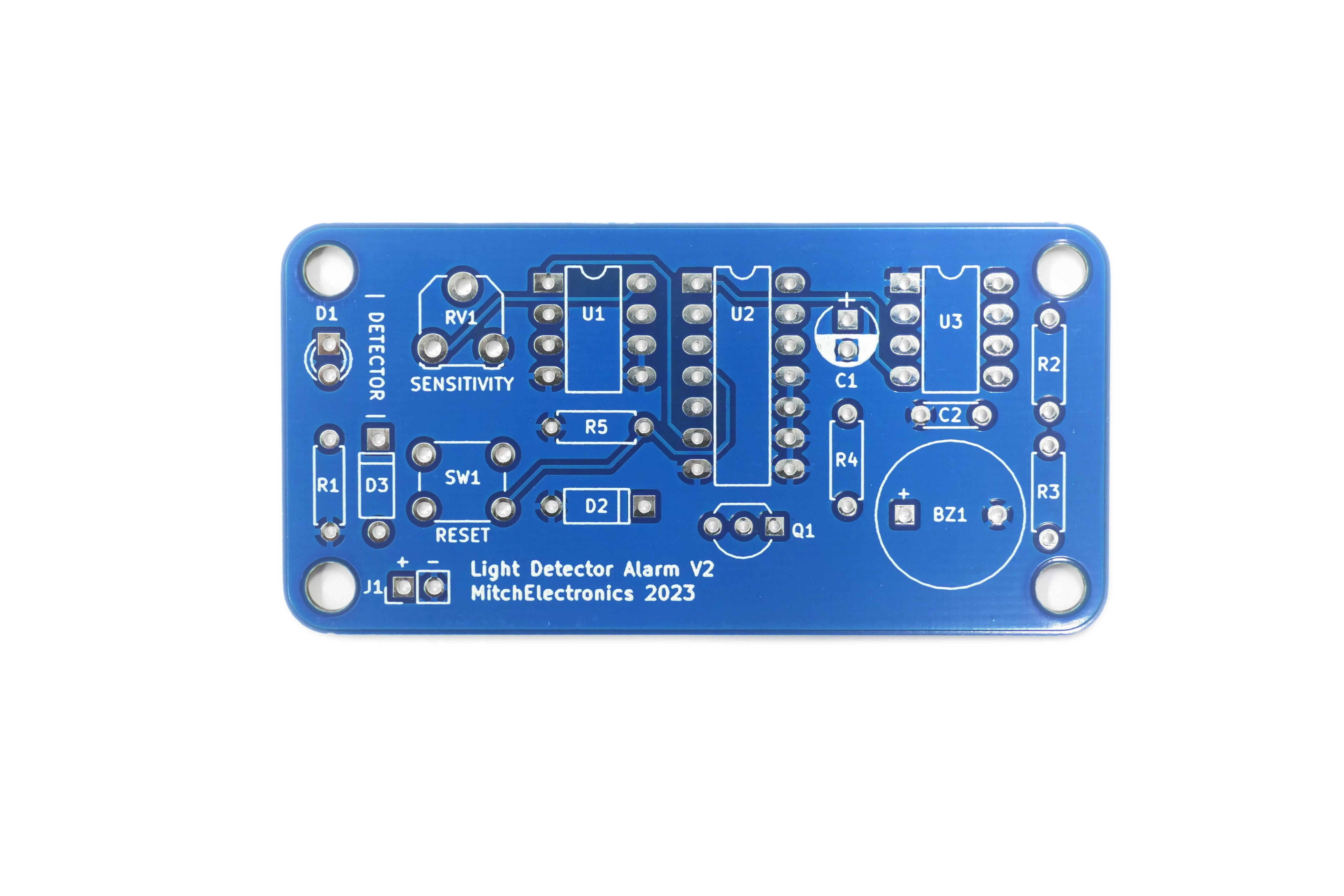
The PCB silkscreen and component references should be checked against the component list before soldering each part.
Before applying power
- Check every component against its PCB reference.
- Confirm the orientation of all polarised components and ICs.
- Inspect for solder bridges, unsoldered pads and clipped leads that could cause a short.
- Check that no loose wire or solder debris remains on the board.
Build with confidence
Construction tips
Recommended build order
A reliable way to assemble Light Alarm Kit is to work from the lowest-profile components to the tallest. This keeps the PCB easy to access while you solder.
- Fit resistors, links and other low-profile components first.
- Fit small capacitors and diodes, checking polarity where applicable.
- Fit IC sockets and small semiconductors, observing the orientation markings.
- Fit larger capacitors, potentiometers, switches and other controls.
- Fit LEDs, connectors and the remaining taller components.
- Insert socketed ICs only after soldering around the socket is complete.
- Inspect every joint and check for solder bridges before applying power.
Electronics construction guidance
If you are new to kit construction, use the Soldering Guide alongside these instructions. Identify each component before fitting it and compare its reference with the component list and PCB silkscreen.
When it does not work
Troubleshooting
Nothing happens when power is applied
- Confirm the supply is connected to the correct input and with the correct polarity.
- Check that ICs, diodes, LEDs, transistors and electrolytic capacitors are fitted in the correct orientation.
- Compare component values and positions against the component list and PCB reference.
- Inspect for missed joints, dry joints and accidental solder bridges.
The circuit powers up but does not behave as expected
This kit is intended for light-level alarm. If the output is stuck, unstable or outside the expected behaviour, use the schematic to trace the circuit a stage at a time rather than replacing several parts at once.
Check the components around the part of the circuit responsible for the output or timing first. A misplaced resistor, reversed semiconductor or poor connection can allow a circuit to power up while preventing it from operating correctly.
The circuit works intermittently
Intermittent behaviour is often caused by a marginal solder joint, a loose connector or a component lead that has not been fully soldered. Gently inspect the board with power removed and reflow any joint that looks dull, cracked or incomplete.
If the fault remains, compare the assembled board with the schematic and PCB reference one connection at a time.
Ready to test and experiment?
Feeling brave? Consider using different resistors and capacitors on the 555 oscillator Move the reset switch externally to the board so only a remote operator can reset the alarm
Once the board is working, compare its behaviour with the schematic and the explanation above. Try changing only one input, control or permitted component value at a time so you can clearly see what effect that change has on the circuit.