
Interactive electronics resource
VU Meter Instructions
Build, understand and experiment with the VU Meter. This resource brings the original kit material into the current MitchElectronics format with the schematic, circuit explanation, component and PCB information, construction guidance, troubleshooting and practical ideas where available.
Introduction
What is the VU Meter Kit?
The MitchElectronics VU Meter kit, as the name suggests, is a VU meter that shows the size of a voltage as an LED bar. These are often seen in music equipment, whereby the relative amplitude of an audio source can quickly be seen, but they can be used in other applications including battery chargers and generic sensor readings.
What does VU stand for?
The term VU stands for Volume Unit, essentially meaning how “loud” a signal is. Due to how voltages work, the value of loudness is entirely relative, so while VU meters show volume units, they are more akin to Voltage Units. Simply put, a VU meter will have a range of voltages it can measure, and the output LED bar chart will essentially show where about that input signal lies between this voltage range.
Why is VU logarithmic?
Answering this question is really interesting because VU meters used in audio equipment are logarithmic, meaning that with each unit, the relative signal strength increases by a factor of 10. This means that a voltage representing an audio signal needs to be multiplied by 10 in order for that audio signal to sound twice as loud.
Why is this the case? Well, it hasn’t anything to do with electronics, but the human ear! Due to how the human brain perceives volume, it takes a signal to be ten times its size to be perceived as being twice as loud.
How can we prove this? Actually, it’s very easy to prove, with the Micro Audio Amp. The potentiometer, which is provided with the kit, is a linear type, which means that as you turn the dial, the amplification factor of the amp also goes up linearly. However, if you listen to the output volume, it doesn’t produce a linear loudness, getting very loud very quickly. This is the nature of hearing!
So, going back to the VU meter, each VU would not be equal to a set voltage, but a change in voltage with respect to the last voltage. The equation that represents VUs is a tad complex, involving logarithms, so we won’t be covering it here.
What about the MitchElectronics VU kit?
For audio applications, it is essential that the VU meter has a logarithmic output, otherwise it would be very hard to work with audio. However, those looking to use the VU meter with battery chargers, sensors, and other linear systems, a logarithmic VU meter would be useless.
So, to address this challenge, we have designed our VU meter to be generic, with the option to choose either a log or linear characteristic depending on the resistors you use. And yes, we provide resistors for both options in the same kit, so you can decide which one you want when you start soldering the kit!
Schematic
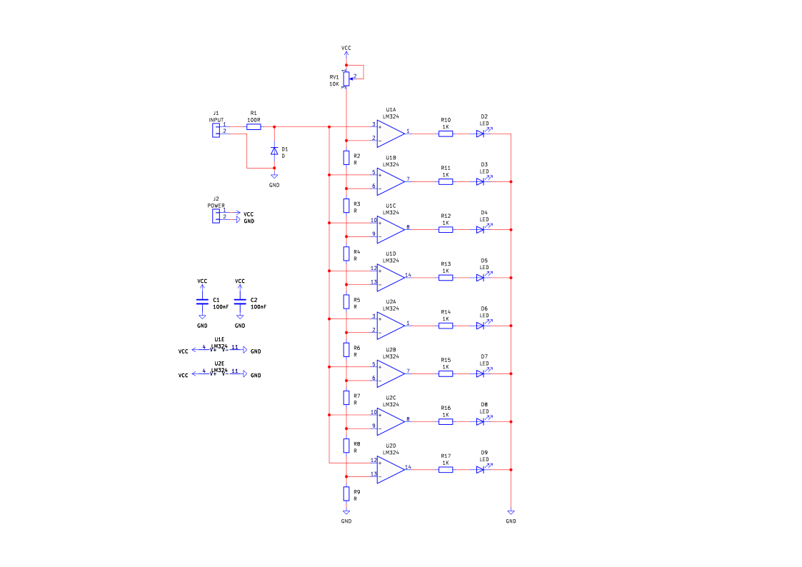
How the VU meter works
While the VU meter kit may look complex, it is surprisingly simple.
To start, there are 8 op-amps that are configured as comparators, meaning that they output a logic signal depending on which of their inputs is larger. If the V+ input is larger than the V- input, then the output of the op-amp will be VCC, otherwise it will be 0V.
Each op-amp has its output connected to its own LED, with LEDS D9 to D5 representing “safe” voltages, D4 and D3 representing “warning voltages”, and D2 representing “danger” voltages.
Each op-am is also connected to the input voltage (the signal being measured), via its non-inverting input (V+), but the inverting input (V-) is connected to a specific point on a long chain of resistors.
Because this resistor chain (R2 to R9) is connected in series, each resistor will have a particular voltage across it, and this voltage will depend on that resistors value compared to the total combination of all the resistors. This means that R9 has the smallest voltage difference (relative to ground), while R2 will have the largest.
This means that the first op-amp, U2D, will output a logic 1 for a very small signal, while the last op-amp, U1A, will output a logic 1 for a large signal, with each op-amp after U2D (going up on the schematic), “activating” for increasingly larger voltages.
If the resistors are of equal sizes, the output LEDs will turn on linearly, such that each specific increase in input voltage (such as 100mV) will cause the next LED to turn on. If, however, each resistor (starting from R9), doubles in value of the previous, the output LEDs will turn on logarithmically.
Lastly, the potentiometer RV1 is used to tune the resistor network, so that the sensitivity of the VU meter can be adjusted.
Project ideas
VU Meter
Well, the name says it all really! This kit is perfect for those looking to add a VU meter to any audio project. By using the logarithmic resistor collection, you will be able to accurately see the loudness of an audio signal, whether it’s the input for a speaker, the output of a microphone, or the volume coming from a musical instrument (preferably synthesizers). In fact, if paired with the Siren LFO Kit, you can make some pretty interesting audio set-ups!

Battery Tester
Interestingly, this kit can also be used as a battery tester, such as those found in cars. By using the linear resistor selection, this kit can be used to detect if a battery is in good condition or not by the voltage it has. This kit could even be integrated into a cars dashboard and directly connected to the battery to show health in transit, but remember, such a project should be done by a professional!
Alarm
For those who are hard of hearing, this VU meter could be a useful device to have on a desk. By connecting the input of the VU meter to an electret microphone kit (such as the IR Sound Sense), this kit can be used to indicate the current volume in the room. Thus, if someone is talking behind you, the VU meter would show this as a change in the display.

Try it yourself
Circuit simulation
What you need
Component List
| Component | Quantity | PCB Reference |
|---|---|---|
| 14 DIP Socket | 2 | U1, U2 |
| LM324 | 2 | U1, U2 |
| 100nF Capacitor | 2 | C1, C2 |
| 100R Resistor | 1 | R1 |
| 1K Resistor | 16 | R2 to R17 (If LIN Version) |
| 1.5K Resistor | 1 | R8 (If LOG Version) |
| 2.2K Resistor | 1 | R7 (If LOG Version) |
| 4.7K Resistor | 1 | R6 (If LOG Version) |
| 15K Resistor | 1 | R5 (If LOG Version) |
| 22K Resistor | 1 | R4 (If LOG Version) |
| 47K Resistor | 1 | R3 (If LOG Version) |
| 100K Resistor | 1 | R2 (If LOG Version) |
| 10K Potentiometer | 1 | RV1 |
| Green LED | 5 | D5 to D9 |
| Yellow LED | 2 | D3, D4 |
| Red LED | 1 | D2 |
| 1N4148 Diode | 1 | D1 |
| Blue Wire | 1 | J1 |
| Black Wire | 1 | J1 |
| PP3 | 1 | J2 |
| VU Meter PCB | 1 | — |
Inspect the board
Interactive BOM
Board reference
PCB & assembly
The PCB silkscreen and component references should be checked against the component list before soldering each part.
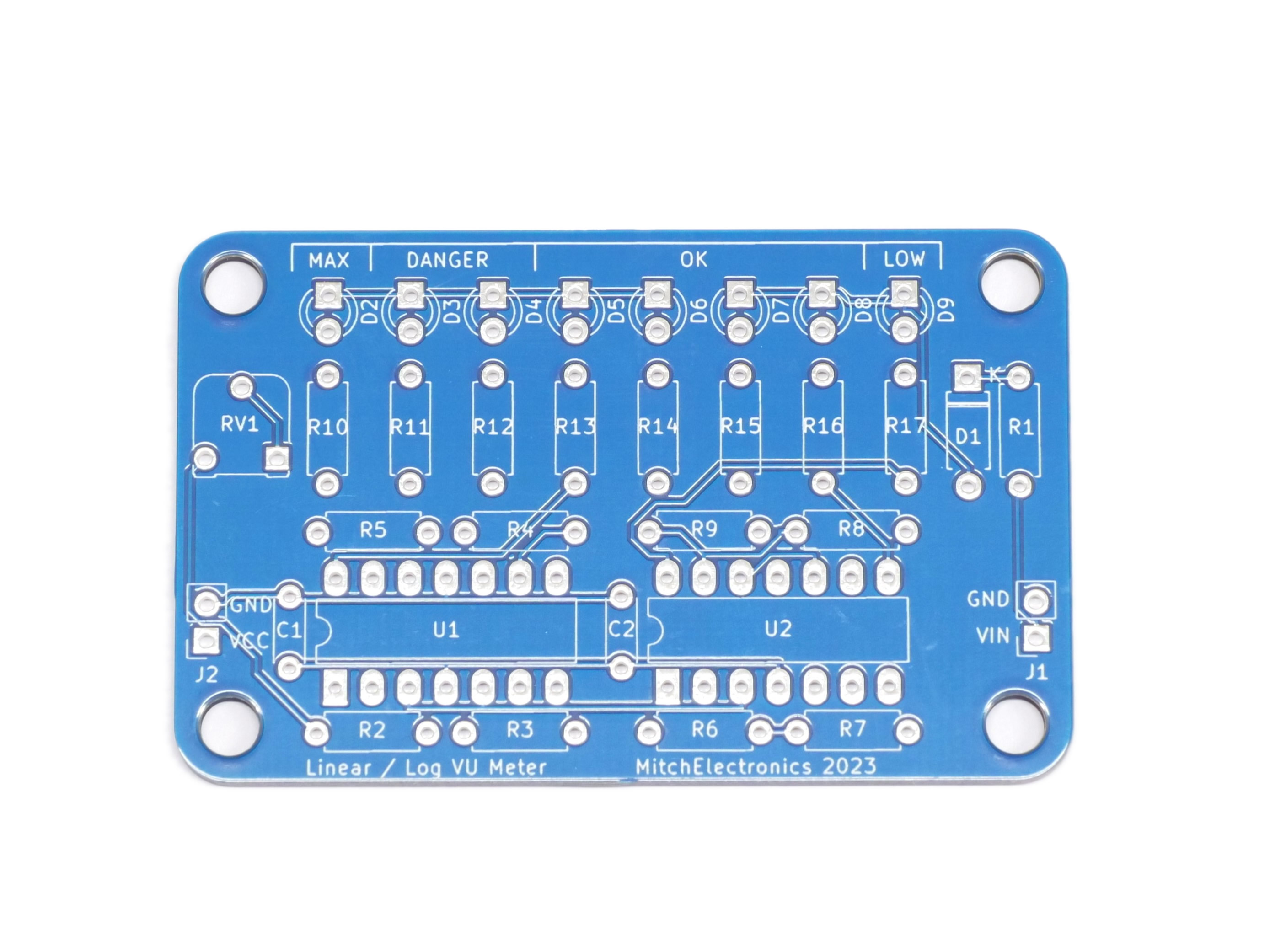
Before applying power
- Check every component against its PCB reference.
- Confirm the orientation of all polarised components and ICs.
- Inspect for solder bridges, unsoldered pads and clipped leads that could cause a short.
- Check that no loose wire or solder debris remains on the board.
Build with confidence
Construction tips
Recommended build order
A reliable way to assemble VU Meter is to work from the lowest-profile components to the tallest. This keeps the PCB easy to access while you solder.
- Fit resistors, links and other low-profile components first.
- Fit small capacitors and diodes, checking polarity where applicable.
- Fit IC sockets and small semiconductors, observing the orientation markings.
- Fit larger capacitors, potentiometers, switches and other controls.
- Fit LEDs, connectors and the remaining taller components.
- Insert socketed ICs only after soldering around the socket is complete.
- Inspect every joint and check for solder bridges before applying power.
Electronics construction guidance
If you are new to kit construction, use the Soldering Guide alongside these instructions. Identify each component before fitting it and compare its reference with the component list and PCB silkscreen.
When it does not work
Troubleshooting
Nothing happens when power is applied
- Confirm the supply is connected to the correct input and with the correct polarity.
- Check that ICs, diodes, LEDs, transistors and electrolytic capacitors are fitted in the correct orientation.
- Compare component values and positions against the component list and PCB reference.
- Inspect for missed joints, dry joints and accidental solder bridges.
The circuit powers up but does not behave as expected
This kit is intended for audio level display. If the output is stuck, unstable or outside the expected behaviour, use the schematic to trace the circuit a stage at a time rather than replacing several parts at once.
Check the components around the part of the circuit responsible for the output or timing first. A misplaced resistor, reversed semiconductor or poor connection can allow a circuit to power up while preventing it from operating correctly.
The circuit works intermittently
Intermittent behaviour is often caused by a marginal solder joint, a loose connector or a component lead that has not been fully soldered. Gently inspect the board with power removed and reflow any joint that looks dull, cracked or incomplete.
If the fault remains, compare the assembled board with the schematic and PCB reference one connection at a time.
Ready to test and experiment?
Once the board is working, compare its behaviour with the schematic and the explanation above. Try changing only one input, control or permitted component value at a time so you can clearly see what effect that change has on the circuit.