
Interactive electronics resource
Voltage Controlled Amplifier Instructions
Build, understand and experiment with the Voltage Controlled Amplifier. This resource brings the original kit material into the current MitchElectronics format with the schematic, circuit explanation, component and PCB information, construction guidance, troubleshooting and practical ideas where available.
Introduction
What is a voltage controlled amplifier?
Voltage-controlled amplifiers (VCAs) have played a crucial role in the evolution of electronic sound processing, particularly in the fields of synthesizers, audio engineering, and signal modulation. Their development can be traced back to the early days of electronic music and telecommunications, where engineers sought a way to dynamically adjust signal levels using control voltages rather than manual potentiometers. In early analog synthesizers, VCAs became an essential component, allowing envelope generators, low-frequency oscillators (LFOs), and other modulation sources to shape sound dynamically. Over time, VCAs also found applications in audio compression, noise gating, and even radio transmission, where precise amplitude control is necessary. While traditional designs relied on transistors or operational amplifiers with varying levels of complexity, modern VCAs have incorporated more sophisticated methods for achieving smooth, linear gain control.
What is the MitchElectronics VCA?
The MitchElectronics Voltage-Controlled Amplifier Kit is a modern and accessible implementation of a VCA, designed for use in analog synthesis, audio processing, and other low-frequency applications. Unlike traditional VCAs that rely on variable transistors, this kit uses an optoisolator—specifically the 4N25—as its core component. The optoisolator provides a more stable and predictable way to control gain, offering improved linearity compared to transistor-based designs. The circuit is based on a non-inverting AC amplifier configuration and operates on a single-rail voltage supply, making it well-suited for modular synthesizers and other electronic music setups. By utilizing an optically controlled resistance element, the MitchElectronics VCA ensures smooth gain modulation with minimal distortion, making it an ideal choice for applications requiring precise voltage-controlled amplification in audio and signal processing environments.
Schematic
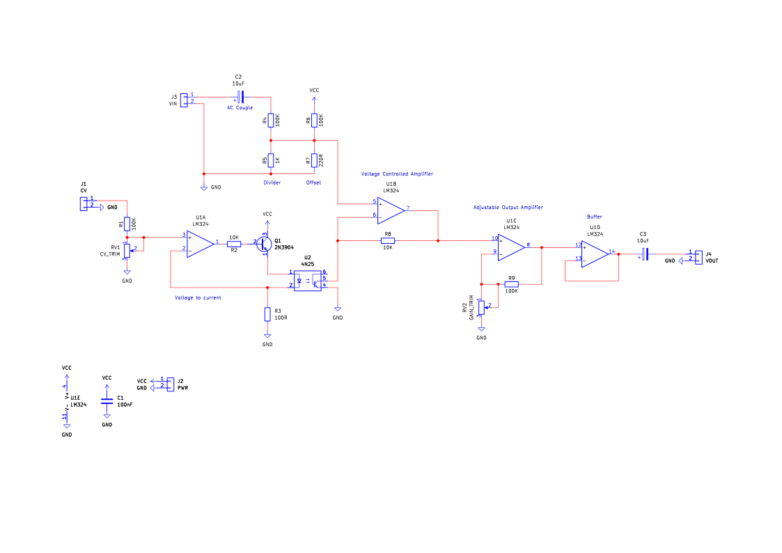
How the voltage controlled amplifier works
The Need For A Voltage-Controlled Resistor
For a voltage-controlled amplifier (VCA) to function effectively, it is necessary to implement a method for creating a voltage-controlled resistor. This is essential because a VCA relies on the ability to dynamically adjust one of the feedback resistors in a non-inverting amplifier circuit. By modifying this resistance in response to an input control voltage, the gain of the amplifier can be adjusted accordingly. Specifically, if the resistance increases in response to a higher control voltage, the gain will also increase, and if the resistance decreases, the gain will be reduced. The challenge, however, lies in finding an effective way to implement a voltage-controlled resistor with precision and stability.
One possible approach to achieving a voltage-controlled resistance is to use a transistor. While transistors can indeed function as voltage-dependent resistors, they introduce several significant challenges. One of the main issues is the inherent variability of transistors, as their characteristics can differ from one device to another, making precise control difficult. Furthermore, transistors exhibit poor linearity, meaning that the relationship between their input voltage and output current is not straightforward or predictable. This non-linearity complicates their use in circuits where precise control of resistance is required. Since most direct voltage-to-resistance conversion methods using transistors suffer from these limitations, an alternative approach is needed. Fortunately, the engineers at MitchElectronics have developed an ingenious solution to this problem.
Introducing The Answer - The Optoisolator
At the core of the MitchElectronics VCA is the 4N25 opto-isolator. The 4N25 is a specialized electronic component that integrates both an LED and a photo-transistor within a single package. This type of device is primarily used in circuits for electrical isolation, allowing signals to be transferred between different parts of a circuit without direct electrical connection. However, beyond its primary function, the 4N25 exhibits a useful characteristic that makes it particularly suitable for implementing a voltage-controlled resistor. Specifically, over a significant operating range, the current flowing through the photo-transistor inside the 4N25 is directly proportional to the brightness of the internal LED. This property allows the 4N25 to function as a current-controlled resistor, which can be used to regulate the gain of a non-inverting amplifier.
However, while the 4N25 provides a means of current-controlled resistance, the goal is to achieve voltage control. Since the 4N25 responds to current rather than voltage, a voltage-to-current conversion stage must be introduced. In this design, the input control voltage is first fed into a voltage-to-current converter circuit. This converter translates the input voltage into a proportional current that drives the LED inside the opto-isolator. As the LED brightness changes in response to the control voltage, the resistance of the photo-transistor also changes, which in turn adjusts the gain of the amplifier. This clever design ensures that the gain of the VCA is adjusted in a linear and predictable manner based on the input control voltage.
Additional Signal Conditioning
One additional challenge arises due to the relatively narrow operating range of the 4N25. The input signal that is being amplified must be carefully adjusted to fall within this operating range. Since the MitchElectronics VCA operates on a single-rail power supply—meaning it has only one voltage source rather than a dual positive and negative supply—it is necessary to AC couple the input signals. AC coupling ensures that the signal is appropriately referenced to a usable voltage level within the circuit’s DC operating range. Additionally, because the opto-isolator operates effectively only within a limited range of resistance values, the input signal must be significantly divided to ensure that the VCA amplifies it correctly within this narrow range.
To further refine the performance of the VCA, a secondary adjustable amplifier stage is included. This additional stage allows the user to fine-tune the gain characteristics of the VCA, ensuring that the output signal maintains an ideal range for a given input signal. This adjustment is particularly useful for applications such as audio processing, where maintaining a consistent and predictable gain response is crucial. Finally, the output signal is AC coupled, meaning that any unwanted DC offset is removed before the signal is sent to the next stage in an audio system. This ensures that the output is clean and suitable for integration into various audio applications, making the MitchElectronics VCA an effective and versatile component in signal processing circuits.
Project ideas
Dynamic Tremolo Effect
Use an LFO to modulate the VCA, creating an adjustable tremolo effect for electric guitar or synthesizers.
Voltage-Controlled Audio Panner
Combine two VCAs to create a stereo panning circuit where the position of an audio signal shifts based on a control voltage.
Envelope-Controlled Amplifier
Design a VCA that responds to an ADSR envelope generator for shaping synthesizer notes dynamically.
Auto-Wah Effect
Utilize an envelope follower to modulate the VCA gain based on input signal amplitude, creating a touch-sensitive wah effect.
Noise Gate for Audio Signals
Implement a noise gate that automatically mutes low-amplitude signals using the VCA.
Amplitude Modulation (AM) Synth
Use the VCA to modulate an audio signal with an external control voltage, generating amplitude-modulated sound effects.
Rhythmic Gating for Beats
Connect a sequencer or drum machine output to control the VCA gain, creating rhythmic gating effects.
Voltage-Controlled Mixer
Combine multiple VCAs to create a mixer where each channel’s volume is voltage-controlled.
Sidechain Compressor for Synths
Use the VCA to duck audio signals in response to a control voltage, similar to a studio sidechain compressor.
VC Equalizer
Develop a multi-band equalizer with voltage-controlled gain for different frequency bands.
Crossfade Mixer
Use two VCAs in an inverse gain configuration to blend between two audio sources dynamically.
Light-Responsive Sound Modulation
Control the VCA with a light sensor to create sound effects based on ambient light levels.
Gesture-Controlled Volume Control
Use a distance sensor to control the gain of the VCA with hand gestures.
Audio Chopper for Glitch Effects
Rapidly modulate the VCA with a high-frequency oscillator for stuttering, glitch-like audio effects.
VC Percussion Generator
Use short voltage pulses to control the VCA, generating percussive clicks and dynamic drum-like sounds.
Amplitude Modulation (AM) Transmitter
Use the VCA to implement AM modulation in a small radio transmitter circuit.
Voltage-Controlled RF Attenuator
Build an RF attenuator where signal strength is adjusted based on a control voltage.
Dynamic Noise Reduction Circuit
Implement a noise suppression system by dynamically adjusting the gain of the amplifier.
Remote Volume Control for Audio Systems
Use a microcontroller to control the VCA, allowing for remote volume adjustments.
Speech Processing & Ducking Circuit
Design a voice-over processing circuit where background audio automatically lowers when speech is detected.
Try it yourself
Circuit simulation
What you need
Component List
Inspect the board
Interactive BOM
Board reference
PCB & assembly
The PCB silkscreen and component references should be checked against the component list before soldering each part.

Before applying power
- Check every component against its PCB reference.
- Confirm the orientation of all polarised components and ICs.
- Inspect for solder bridges, unsoldered pads and clipped leads that could cause a short.
- Check that no loose wire or solder debris remains on the board.
Build with confidence
Construction tips
Recommended build order
A reliable way to assemble Voltage Controlled Amplifier is to work from the lowest-profile components to the tallest. This keeps the PCB easy to access while you solder.
- Fit resistors, links and other low-profile components first.
- Fit small capacitors and diodes, checking polarity where applicable.
- Fit IC sockets and small semiconductors, observing the orientation markings.
- Fit larger capacitors, potentiometers, switches and other controls.
- Fit LEDs, connectors and the remaining taller components.
- Insert socketed ICs only after soldering around the socket is complete.
- Inspect every joint and check for solder bridges before applying power.
Electronics construction guidance
If you are new to kit construction, use the Soldering Guide alongside these instructions. Identify each component before fitting it and compare its reference with the component list and PCB silkscreen.
When it does not work
Troubleshooting
Nothing happens when power is applied
- Confirm the supply is connected to the correct input and with the correct polarity.
- Check that ICs, diodes, LEDs, transistors and electrolytic capacitors are fitted in the correct orientation.
- Compare component values and positions against the component list and PCB reference.
- Inspect for missed joints, dry joints and accidental solder bridges.
The circuit powers up but does not behave as expected
This kit is intended for voltage-controlled analogue amplifier. If the output is stuck, unstable or outside the expected behaviour, use the schematic to trace the circuit a stage at a time rather than replacing several parts at once.
Check the components around the part of the circuit responsible for the output or timing first. A misplaced resistor, reversed semiconductor or poor connection can allow a circuit to power up while preventing it from operating correctly.
The circuit works intermittently
Intermittent behaviour is often caused by a marginal solder joint, a loose connector or a component lead that has not been fully soldered. Gently inspect the board with power removed and reflow any joint that looks dull, cracked or incomplete.
If the fault remains, compare the assembled board with the schematic and PCB reference one connection at a time.
Ready to test and experiment?
Enhance the VCA by incorporating a microcontroller (such as an Arduino or Raspberry Pi) to enable precise digital control, automation, and MIDI integration for advanced audio applications.
Optimize the circuit for a wider frequency range by experimenting with different optoisolators or active components, making it suitable for both low-frequency modulation and high-frequency signal processing.
Combine multiple VCAs in series or parallel to create dynamic signal processing effects such as compression, multi-band equalization, or complex amplitude modulation.
Once the board is working, compare its behaviour with the schematic and the explanation above. Try changing only one input, control or permitted component value at a time so you can clearly see what effect that change has on the circuit.