
Interactive electronics resource
Temperature Sense Kit Instructions
Build, understand and experiment with the Temperature Sense Kit. This resource brings the original kit material into the current MitchElectronics format with the schematic, circuit explanation, component and PCB information, construction guidance, troubleshooting and practical ideas where available.
Introduction
What is the SENSE range?
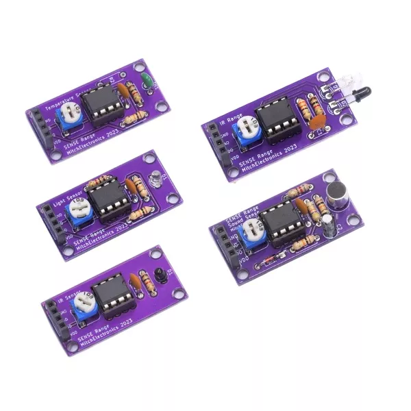
The SENSE Range are electronic kits that let you build your own module with sensing capabilities. Each module has the exact same dimensions, pin-out, and hole location so that modules can be interchanged depending on what needs detecting. For example, the Sound Sense is capable of detecting sound, while the Temp Sense uses a thermistor to detect the ambient temperature.
Unlike other sensing modules on the market, the simplicity of the MitchElectronics Sense Range makes them easy to modify, use in other circuits, and build. At the same time, the standardised 40mm x 20mm dimension is very easy to work with when creating enclosures and mounting a Sense board.
What is the standard pin-out for the SENSE range?
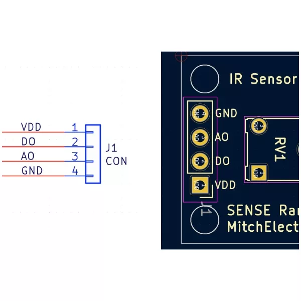
To make using the Sense Range as easy as possible, all Sense kits have a four pin connector that is identical for each device. Two of these pins are for providing power (VCC and 0V), and the other two are one digital output (that switches between VCC and 0V), and analogue output, which varies depending on the signal being sensed. For example, the Sound Sense produces an analogue signal whose amplitude increases with sound volume, while the Temp Sense produces a voltage that directly relates to temperature.
What is the standard dimension of the SENSE range?
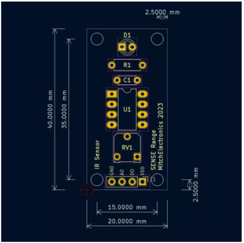
To make sure that using the Sense Range is as simple as possible, all dimensions, hole sizes, and positions are identical across all modules. By doing so, modules can be swapped around without needing to change enclosures, screws, or mountings. At the same time, this standardisation also allows for modules to be stacked in frames which can also be convenient
The standard size for all kits is 40mm x 20mm, M2 holes (2mm diameter), a hole separation of 35mm x 15mm, and a hole edge spacing of 2.5mm.
Schematic
How does the temp sense work?
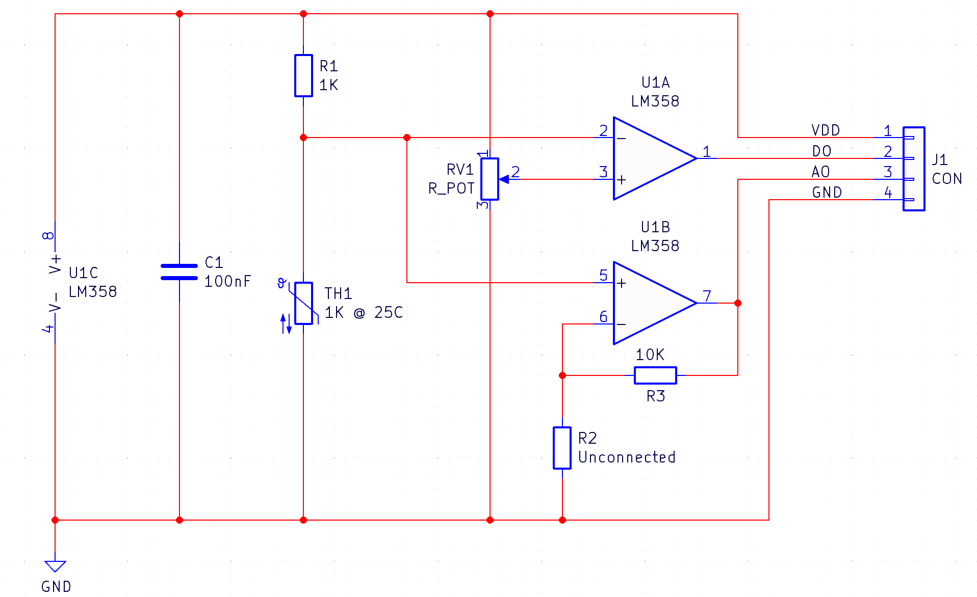
The Temp Sense consists of three different circuits; a thermistor-driven potential divider (TH1 and R1), a comparator (U1A), and a unity gain buffer (U1B) with optional gain via R2.
The thermistor potential divider, made using the thermistor TH1 and resistor R1, produces a varying voltage across the thermistor depending on the temperature of the thermistor. The thermistor used in the Temp Sense is a Negative Temperature Coefficient (NTC) variety with a nominal resistance of 1KΩ at 25˚C, meaning that as the temperature rises, the resistance of the thermistor decreases.
As such, the output voltage across the thermistor decreases with an increase in temperature and increases with a decrease in temperature. In an ideal world, the output voltage of this stage would be 2.5V for a temperature of 25˚C when powered by a 5V supply, but the variation in tolerance will result in a different reading (albeit very close).
The voltage across the thermistor is fed into two different op-amps; one configured as a comparator (U1A), and one configured as a unity gain amplifier (U1B). The comparator U1A has its positive input connected to a potentiometer which determines the trigger point of the comparator. This means that when the voltage of the potentiometer is greater than the thermistor, the output of the comparator is VCC (logic one), and when the voltage of the potentiometer is lower than the thermistor, the output of the comparator is 0V (logic zero). Overall, this means that the comparator indicates whether the temperature is above a specific value (i.e., VCC = too hot and 0V == too cold).
The unity gain amplifier U1B simply copies the voltage from the thermistor onto its output, enabling external circuits to read the voltage of the thermistor without affecting it. R2 has been left unconnected so that U1B acts as a unity gain amplifier, but inserting a resistor here will result in U1B acting as a non-inverting amplifier. For most applications, its recommended to leave R2 unpopulated.
Project ideas
Environmental Monitor
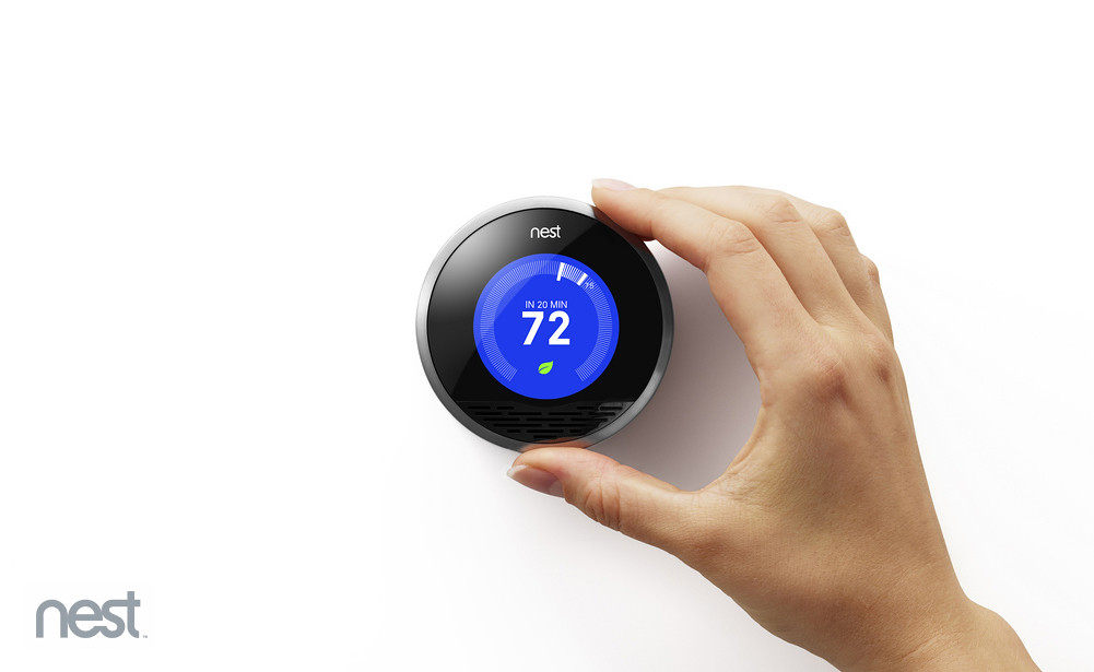
By connecting the analogue output of the Temp Sense to the ADC input of an MCU, it is possible to read the ambient temperature. This can be used to create advanced thermostats that intelligently respond to changes in ambient temperature, IoT devices that log environmental conditions, and even safety devices that monitor for dramatic temperature swings.
Active Cooling
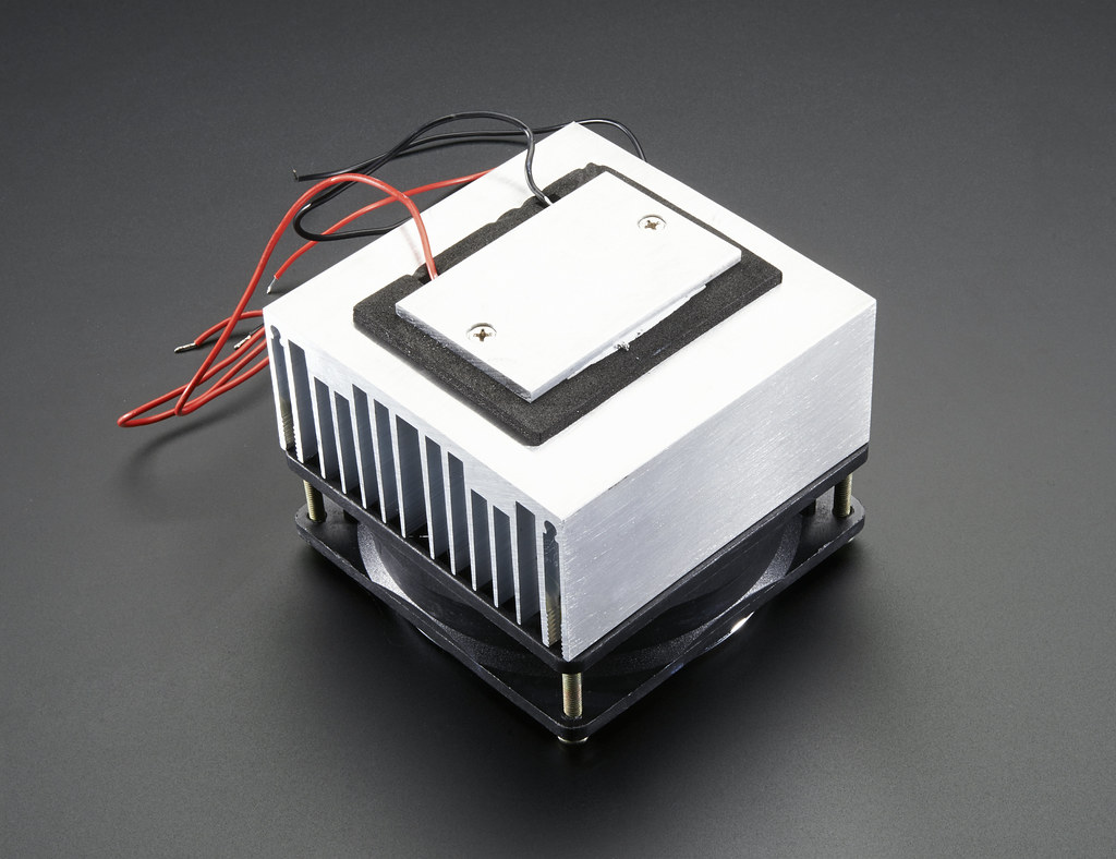
Projects that deal with large powers can quickly overheat if not cooled down properly, which is why heatsinks and fans are commonly found in electronic devices. But running a fan at maximum speed is both noisy and energy wasteful, especially if the device being cooled only gets hot at specific times.
The Temp Sense can be used to control an external fan to turn on and off depending on the internal temperature of a project, and such circuits are commonly found in computers, laptops, and power supplies.
Reaction Monitor
For those interested in chemistry, the thermistor can be used to monitor chemical reactions, and combining the Temp Sense with an MCU allows for the plotting of temperature over time.
For example, a fermentation tank used to brew beer can be actively monitored to ensure the correct temperature, and produce a warning if the temperature changes too much. Another example would be monitoring the reaction between two highly reactive compounds that need to be kept cool (such as aluminium and hydrochloric acid). This reaction generates hydrogen as well as a lot of heat, and this heat, if left unchecked, can ignite the hydrogen!
But remember, MitchElectronics kits are only for educational use in non-safety critical applications!

Try it yourself
Circuit simulation
What you need
Component List
| Component | Quantity | PCB Reference |
|---|---|---|
| LM358 | 1 | U1 |
| 8 DIP Socket | 1 | U1 |
| 1KΩ NTC Thermistor | 1 | TH1 |
| 1KΩ Resistor | 1 | R1, R2 (R2 Optional) |
| 10KΩ Resistor | 1 | R3 |
| 100nF Capacitor | 1 | C1 |
| 10KΩ Potentiometer | 1 | RV1 |
| 4-Way Socket | 1 | J1 |
| Temp Sense PCB | 1 | — |
Inspect the board
Interactive BOM
Board reference
PCB & assembly
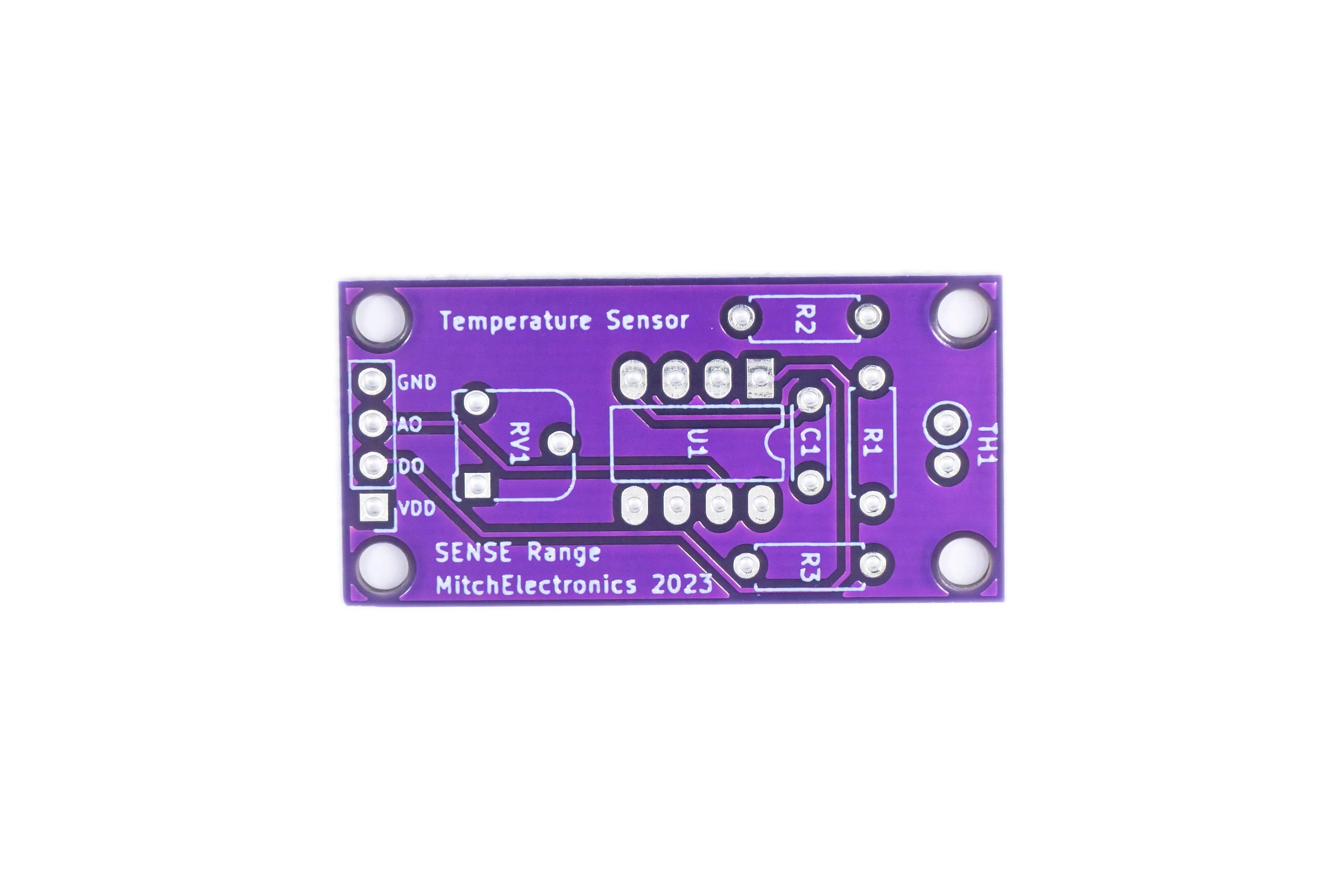
The PCB silkscreen and component references should be checked against the component list before soldering each part.
Before applying power
- Check every component against its PCB reference.
- Confirm the orientation of all polarised components and ICs.
- Inspect for solder bridges, unsoldered pads and clipped leads that could cause a short.
- Check that no loose wire or solder debris remains on the board.
Build with confidence
Construction tips
Recommended build order
A reliable way to assemble Temperature Sense Kit is to work from the lowest-profile components to the tallest. This keeps the PCB easy to access while you solder.
- Fit resistors, links and other low-profile components first.
- Fit small capacitors and diodes, checking polarity where applicable.
- Fit IC sockets and small semiconductors, observing the orientation markings.
- Fit larger capacitors, potentiometers, switches and other controls.
- Fit LEDs, connectors and the remaining taller components.
- Insert socketed ICs only after soldering around the socket is complete.
- Inspect every joint and check for solder bridges before applying power.
Electronics construction guidance
If you are new to kit construction, use the Soldering Guide alongside these instructions. Identify each component before fitting it and compare its reference with the component list and PCB silkscreen.
When it does not work
Troubleshooting
Nothing happens when power is applied
- Confirm the supply is connected to the correct input and with the correct polarity.
- Check that ICs, diodes, LEDs, transistors and electrolytic capacitors are fitted in the correct orientation.
- Compare component values and positions against the component list and PCB reference.
- Inspect for missed joints, dry joints and accidental solder bridges.
The circuit powers up but does not behave as expected
This kit is intended for temperature sensing module. If the output is stuck, unstable or outside the expected behaviour, use the schematic to trace the circuit a stage at a time rather than replacing several parts at once.
Check the components around the part of the circuit responsible for the output or timing first. A misplaced resistor, reversed semiconductor or poor connection can allow a circuit to power up while preventing it from operating correctly.
The circuit works intermittently
Intermittent behaviour is often caused by a marginal solder joint, a loose connector or a component lead that has not been fully soldered. Gently inspect the board with power removed and reflow any joint that looks dull, cracked or incomplete.
If the fault remains, compare the assembled board with the schematic and PCB reference one connection at a time.
Ready to test and experiment?
Feeling brave? Consider using different resistors Can be done to change the sensitivity of the amplifier
Once the board is working, compare its behaviour with the schematic and the explanation above. Try changing only one input, control or permitted component value at a time so you can clearly see what effect that change has on the circuit.