More rigid construction
Paper-phenolic prototyping boards can flex, chip and suffer track damage during repeated handling. FR4 gives the ME range a much more PCB-like mechanical base.

Modern prototyping hardware
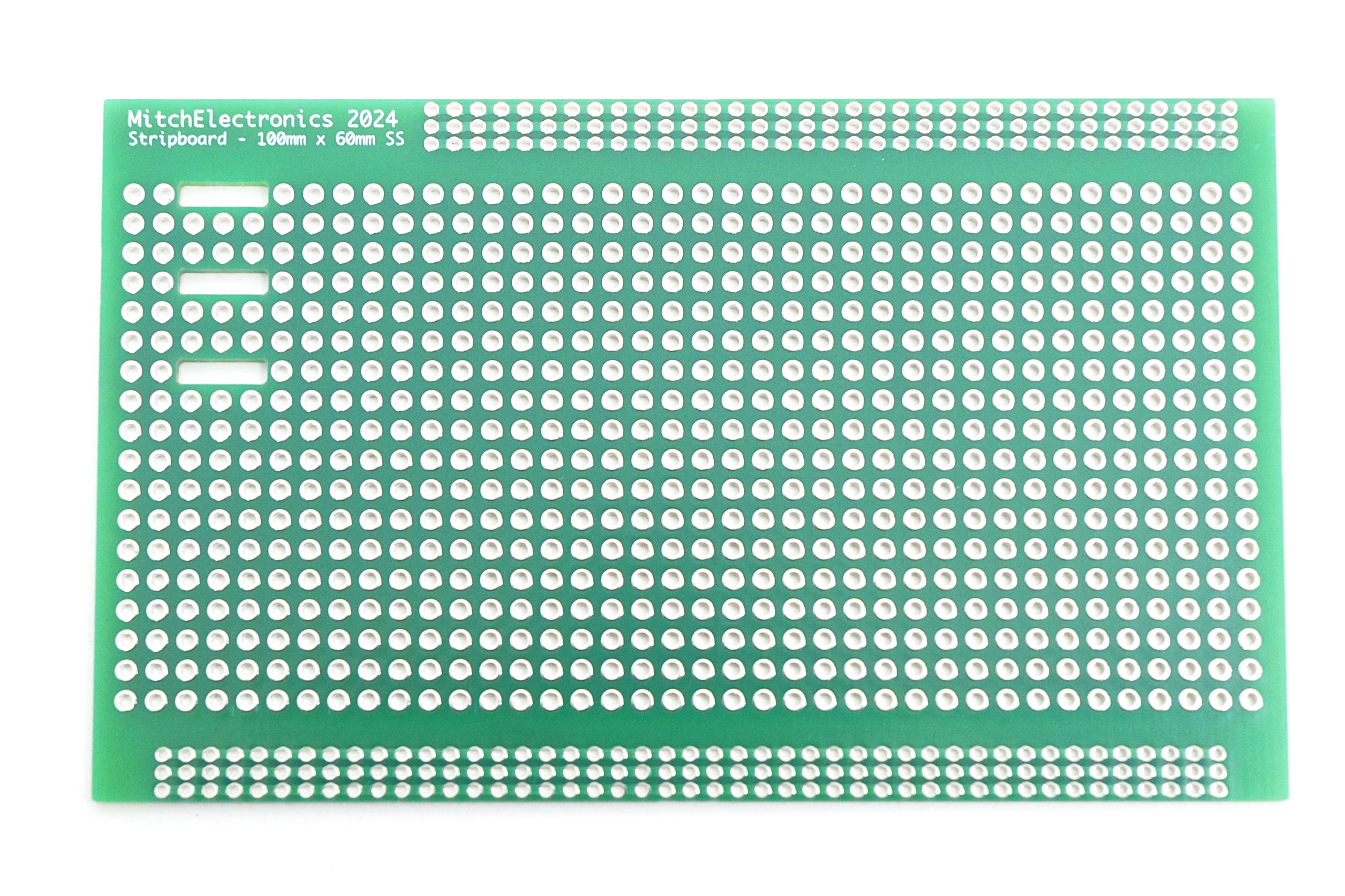
ME Stripboards take the speed and flexibility of traditional stripboard and combine it with FR4 construction, plated holes, improved power distribution, practical cable management, and options for both through-hole and surface-mount designs.
What is stripboard?
Stripboard gives you a regular grid of copper-connected positions that can be cut, linked and populated to create a permanent circuit without designing a dedicated printed circuit board first.
Breadboards are excellent while a circuit is changing every few minutes, but eventually a prototype needs to survive handling, transport and real-world testing. A custom PCB solves that problem, although it also introduces design time, fabrication lead time and a layout that is fixed once ordered.
Stripboard sits neatly between the two. Components are soldered in place, copper tracks provide repeated connection points, and individual tracks can be isolated wherever the circuit requires. Wire links can then bridge between rows or sections to create the required topology.
ME Stripboards keep that simple workflow while updating the physical board around it. Instead of treating stripboard as disposable prototyping material, the range is designed to be robust enough for projects that may be assembled, modified and kept in service for much longer.
It is particularly useful for one-offs, laboratory fixtures, teaching projects, test interfaces, repairs, proof-of-concept hardware and low-volume builds where flexibility matters more than production optimisation.
Why redesign stripboard?
Traditional stripboard is still useful, but low-cost versions often make compromises in substrate quality, pad strength, routing options and component pitch. Those limitations become much more noticeable once a prototype moves beyond a quick bench experiment.
Paper-phenolic prototyping boards can flex, chip and suffer track damage during repeated handling. FR4 gives the ME range a much more PCB-like mechanical base.
Lead-free assembly and rework can expose a board to significant heat. FR4 and plated holes provide a more forgiving platform when joints need to be assembled, inspected or reworked.
A single layer is ideal for straightforward work, while the double-sided board adds another routing plane when a design becomes denser or needs more freedom around components.
Modern electronics increasingly uses surface-mount packages. The dedicated SMD board uses a 1.27mm pitch so parts such as SOIC devices can be prototyped without a separate breakout PCB.
Designed around real builds
The range is not only about changing the substrate. The board layouts add practical details intended to make wiring, power distribution and mixed-component prototyping cleaner.
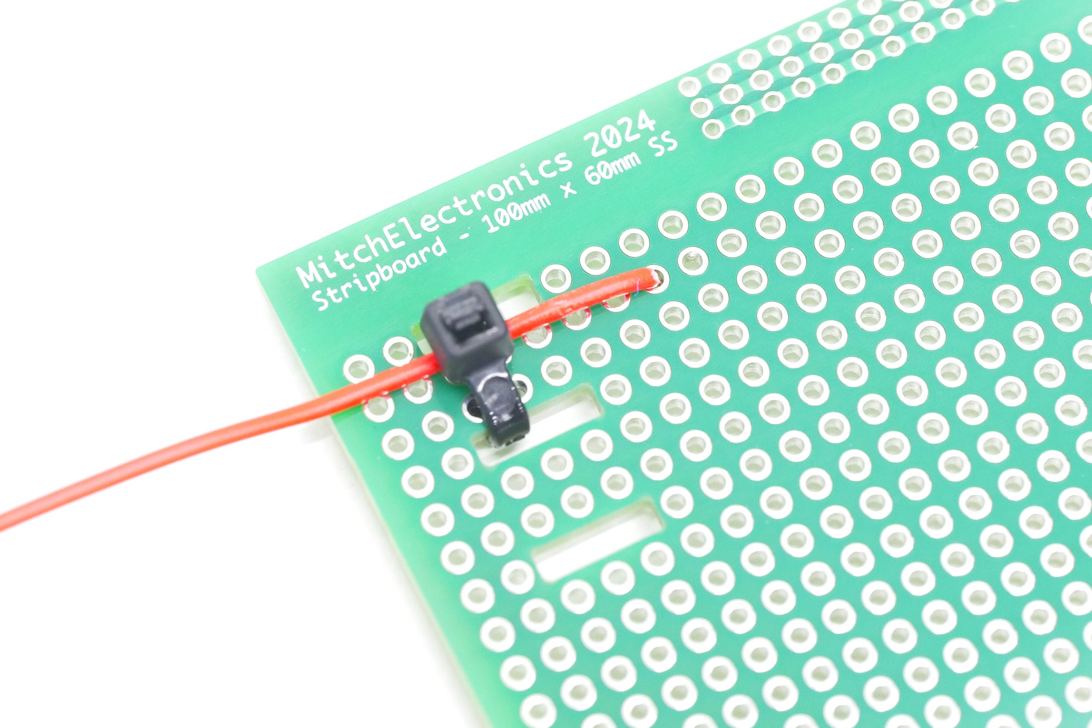
External wiring is often the weakest mechanical point in a hand-built prototype. Dedicated slots allow wires or small cable bundles to be tied to the board so movement is not transferred directly into solder joints.
That gives simple strain relief without needing to drill the board or add a separate mechanical bracket.
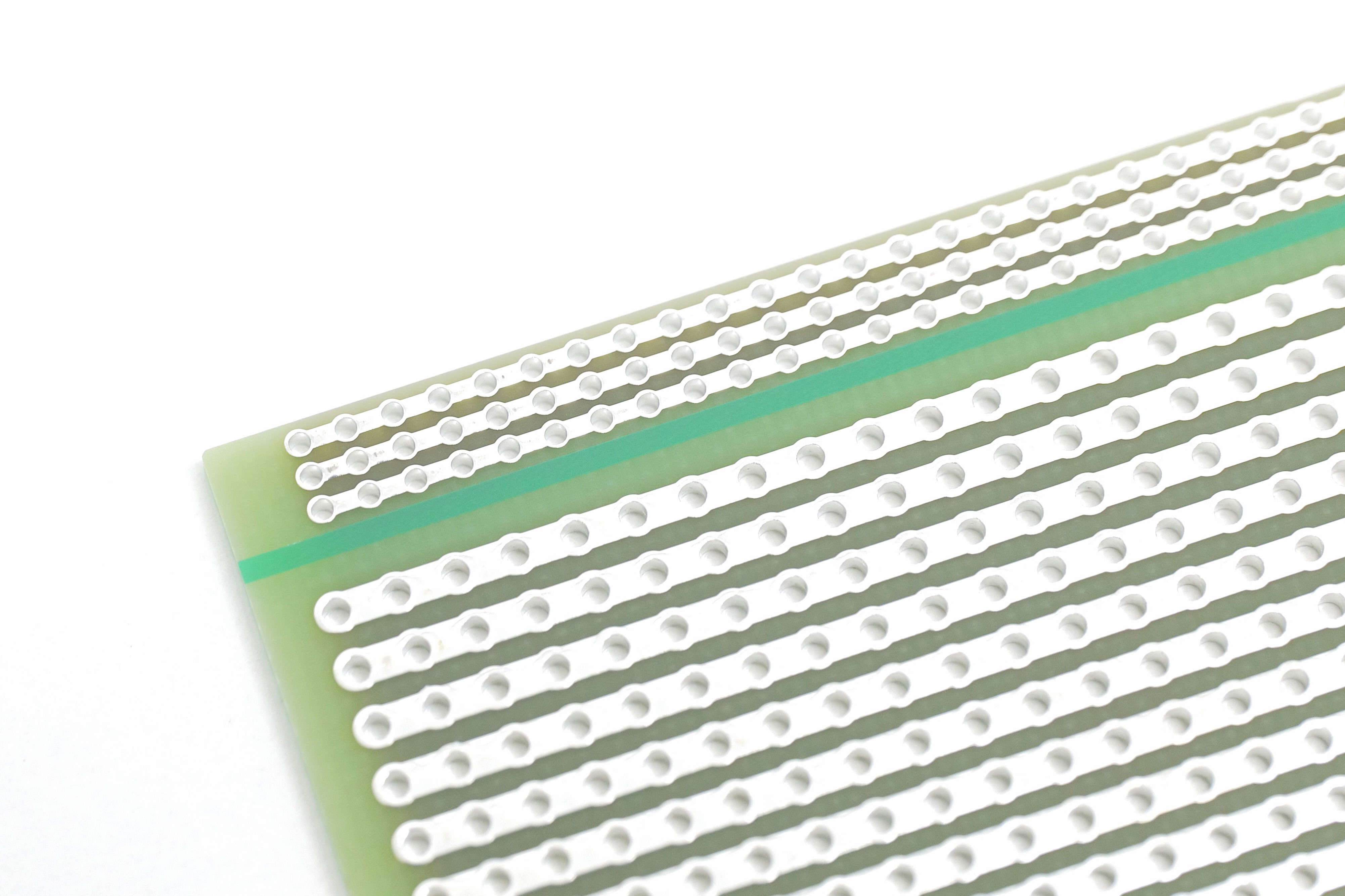
Power and ground tend to collect more connections than any other nets in a prototype. Dedicated rail areas provide many connection points so supply wiring does not have to consume useful signal tracks.
The result is a cleaner layout and a more obvious place to bring power into the circuit, distribute it, and attach measurement points.
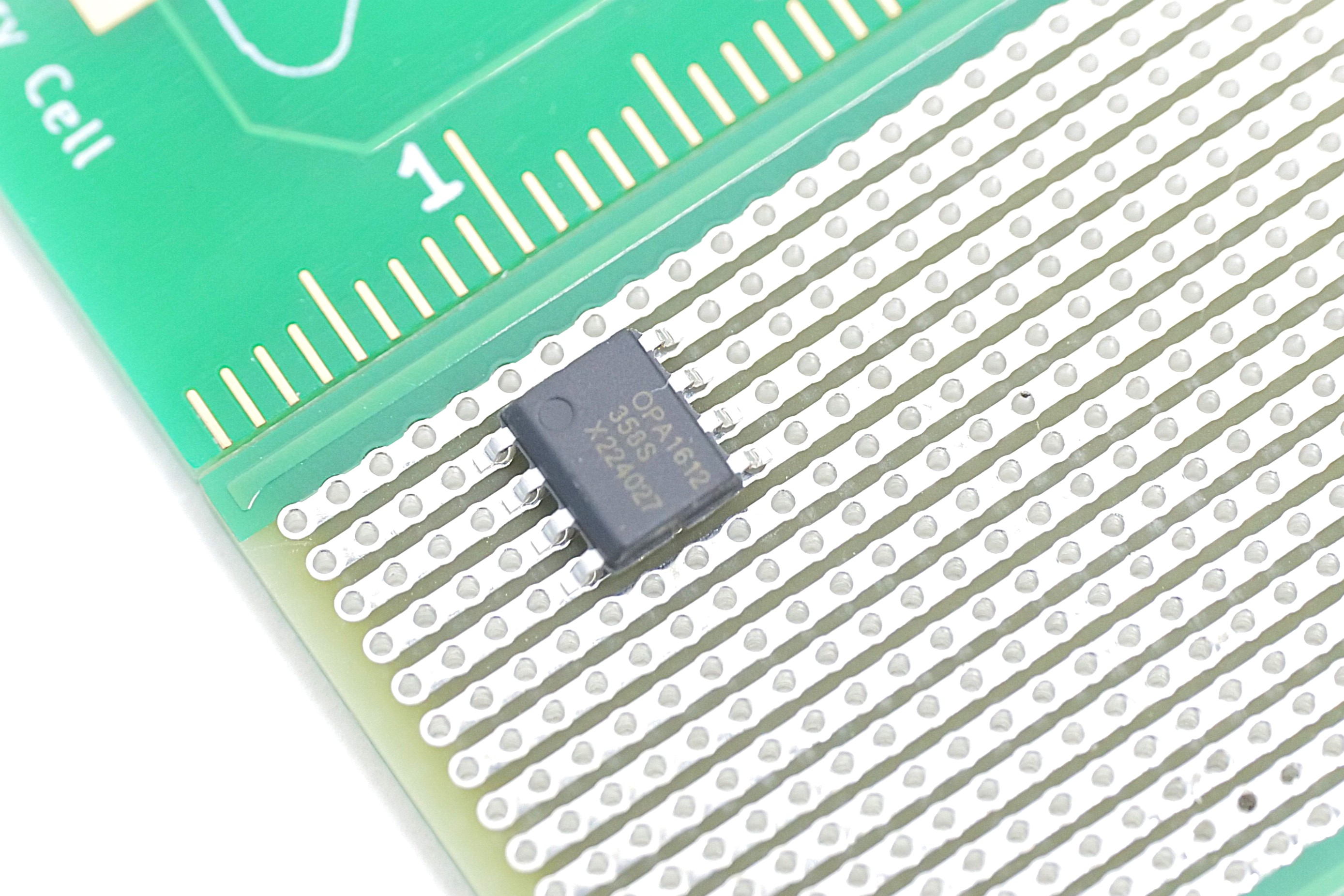
The SMD stripboard adapts the same track-based idea to a finer 1.27mm pitch. This makes it possible to mount common surface-mount packages directly on a prototyping board instead of first soldering them onto a breakout adapter.
It is useful for modern regulators, op-amps, logic and other devices that are increasingly difficult to obtain in through-hole packages.
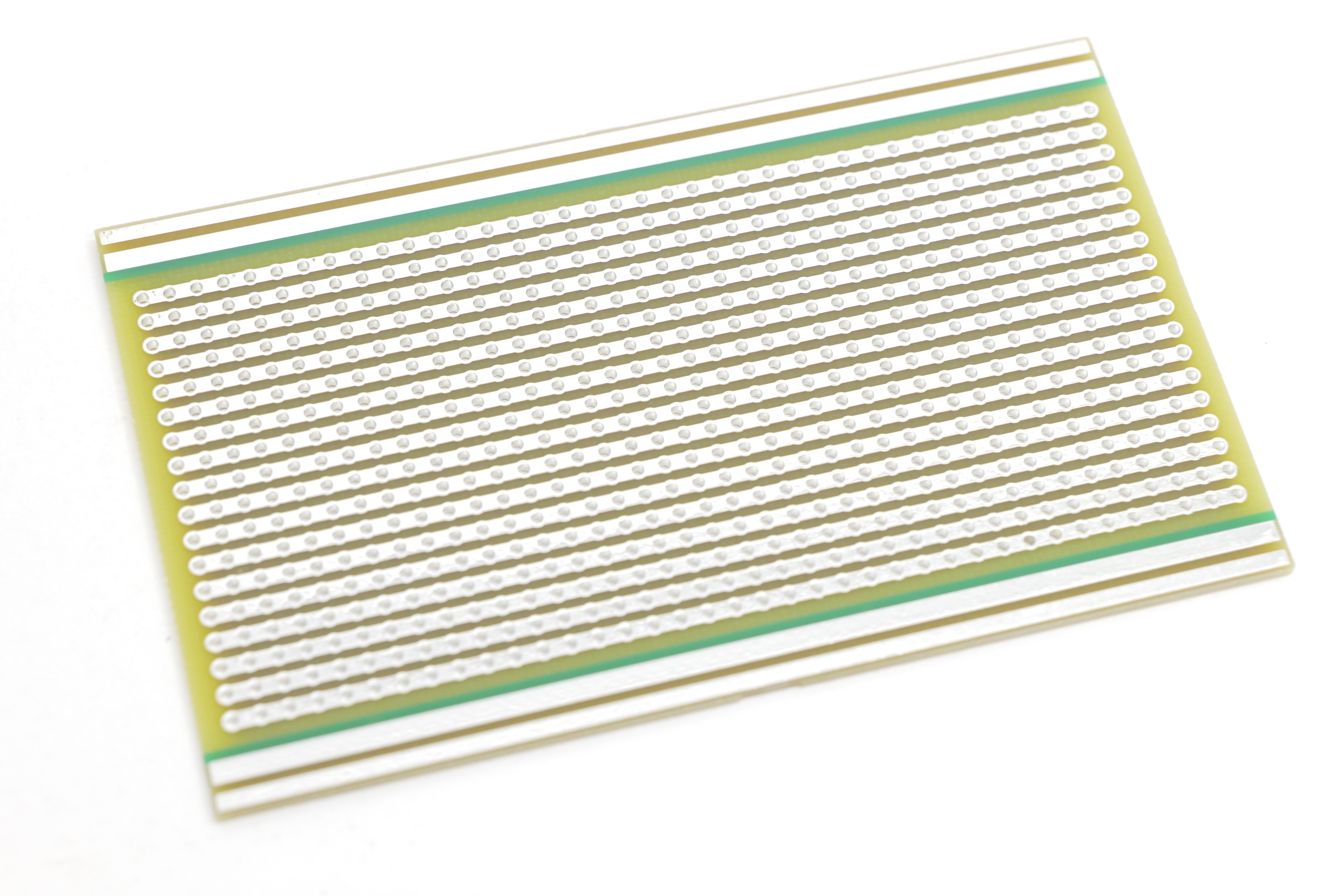
The double-sided 100 × 60mm version provides conductive routing on both sides of the board. That creates far more options for dense layouts and reduces the number of long jumper wires needed to cross existing connections.
Plated-through holes connect the board structure through each position, giving the design a much more PCB-like approach to prototyping.
ME Stripboard range
The three formats cover straightforward through-hole circuits, denser double-sided layouts and small surface-mount prototypes.
The general-purpose option for breadboard-style circuits, educational projects, test fixtures and permanent one-off builds.
More routing freedom for dense circuits where a single copper layer would require too many jumper wires or awkward compromises.
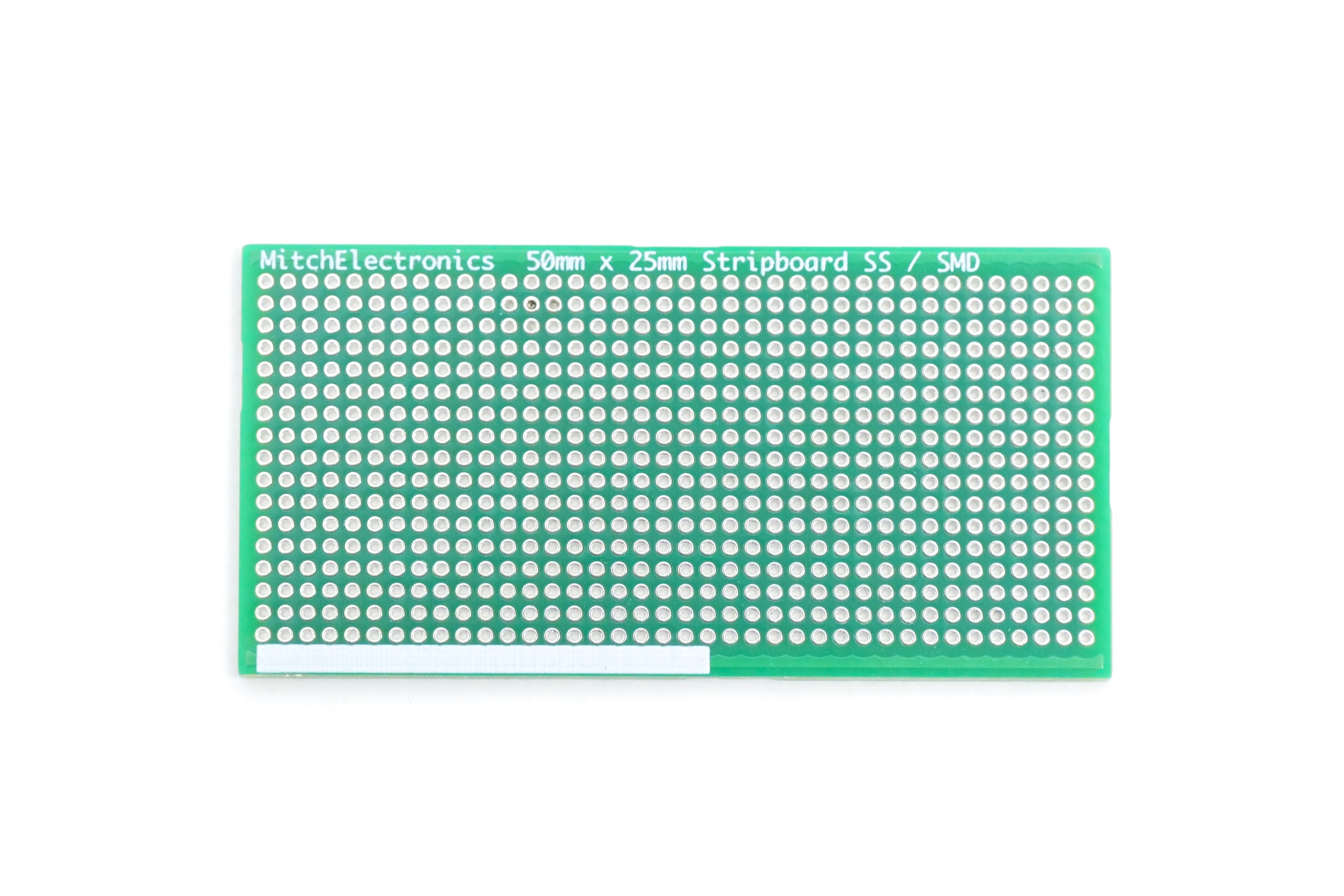
A compact 1.27mm-pitch board for prototyping modern surface-mount circuits without having to turn every device into a through-hole module first.
Which one should I use?
The right stripboard is mainly determined by the parts you need to fit and how many connections have to cross one another.
| Requirement | 100 × 60 SS | 100 × 60 DS | 50 × 25 SMD |
|---|---|---|---|
| Through-hole components | Excellent | Excellent | No |
| Surface-mount components | Limited | Limited | Designed for it |
| Simple circuits | Ideal | More than needed | For SMD designs |
| Dense routing | Good | Best choice | Compact SMD |
| Breadboard migration | Very easy | Very easy | Different pitch |
Stripboard tracks are continuous until you intentionally isolate them. Mark cuts before assembly and verify them with a continuity tester before applying power.
Place connectors, ICs and large components first on paper or in a simple grid drawing. A little planning greatly reduces long wire links and difficult rework later.
For higher-current paths, power conversion or thermally demanding parts, consider conductor width, temperature rise and connection resistance rather than assuming every track suits every load.
From prototype to something you can keep
Choose a through-hole or SMD format, move beyond the breadboard, and keep enough flexibility to change the circuit while you are still learning from it.