
Interactive electronics resource
Sound Alarm Kit Instructions
Build, understand and experiment with the Sound Alarm Kit. This resource brings the original kit material into the current MitchElectronics format with the schematic, circuit explanation, component and PCB information, construction guidance, troubleshooting and practical ideas where available.
Introduction
The Sound Alarm Kit, as the name suggests, lets you build a sound-activated alarm. An onboard microphone listens for sound waves that get turned into electrical signals, and these signals are then amplified by a non-inverting amplifier. From there, a comparator checks to see if the detected sound is above a threshold, and if so, an alarm circuit is triggered.
The detection circuitry uses a latch to remember the detection of sound. By doing so, the sounder will continue to beep even if the surroundings become quiet. A small reset switch on the board allows users to reset the beeper, thus rearming the device.
Schematic
How does the sound alarm work?
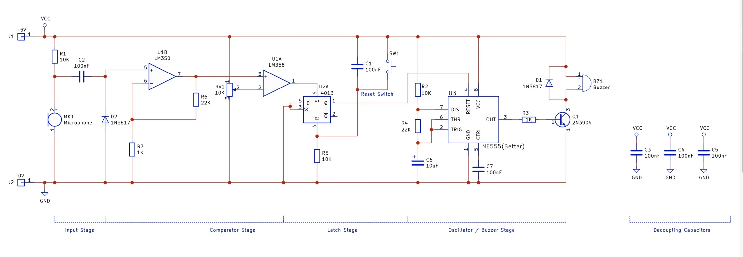
The Sound Alarm Kit is made up of four different stages; the input stage from the microphone, a comparator stage, a latch stage, and an oscillator stage.
The first stage receives signals from an electret microphone (MK1) and couples the signal to an op-amp (U1B) via a capacitor (C2). A reverse-biased diode (D2) is used to remove the negative portion of the incoming signal, as this can cause the op-amp to behave erratically. This op-amp also amplifies the sound signal by around 22x, which makes detecting the signal easier in the next stage (using resistors R7 and R6).
The next stage is a comparator (U1A). The comparator compares the signal from the amplified microphone stage to a potentiometer (RV1), and if the signal becomes greater than the output of the potentiometer, then the output of the comparator switches on (VCC). This causes the next stage, the latch (U2A), to switch on and stay on until the reset button (SW1) is pressed. The latch used in this circuit is from a 4013 dual D-type flip-flop that is capable of more than just a simple latch, however, these other configurations are not needed in this circuit.
The last stage is a 555 astable oscillator whose reset line is controlled by the latch stage. Under normal conditions(i.e., the latch output being low), the 555 astable oscillator is disabled as the RESET pin to the 555 is held low.However, when a sound signal is detected, the 555 begins to oscillate, and the result is the transistor (Q1) beingturned on and off. This turning off and on of the transistor also turns the buzzer BZ1 off and on.
Notes on using the circuit:
This circuit requires a 5V power source which can be obtained with either the Simple Power Supply Kit that conveniently converts a 9V battery into a 5V output, or from the Simple Power Module SMD Trainer Kit.
The potentiometer is used to adjust the sensitivity, so use that when setting the sensitivity of your alarm system!
Project ideas
Burglar Alarm
One of the best uses for this kit is as a burglar alarm. By placing this circuit near your valuables, anyone who attempts to burgle your valuables and accidentally makes too much noise will trigger the circuit, alerting you and others of the burglary in progress

Peak Volume Detector
If you have neighbours who particularly dislike loud noises, you can use this kit to alert you if you are making too much noise. Simply set the detection level of the alarm to the maximum volume permitted, and then go about your day. If the alarm sounds, just keep it down!

Try it yourself
Circuit simulation
Not available in mobile view
What you need
Component List
| Component | Quantity | PCB Reference |
|---|---|---|
| 8 DIP Socket | 2 | U1, U3 |
| 14 DIP Socket | 1 | U2 |
| LM358 | 1 | U1 |
| NE555 | 1 | U3 |
| 4013 | 1 | U2 |
| 100nF Capacitor | 6 | C1, C2, C3, C4, C5, C7 |
| 10uF Capacitor | 1 | C6 |
| 1KΩ Resistor | 2 | R3, R7 |
| 10KΩ Resistor | 3 | R1, R2, R5 |
| 22KΩ Resistor | 2 | R4, R6 |
| 10KΩ Potentiometer | 1 | RV1 |
| 1N5817 Diode | 2 | D1, D2 |
| 2N3904 | 1 | Q1 |
| Electret Microphone | 1 | MK1 |
| Buzzer | 1 | BZ1 |
| Tactile Switch | 1 | SW1 |
| Black Wire | 1 | 0V |
| Red Wire | 1 | +5V |
| Sound Alarm PCB | 1 | — |
Inspect the board
Interactive BOM
Board reference
PCB & assembly
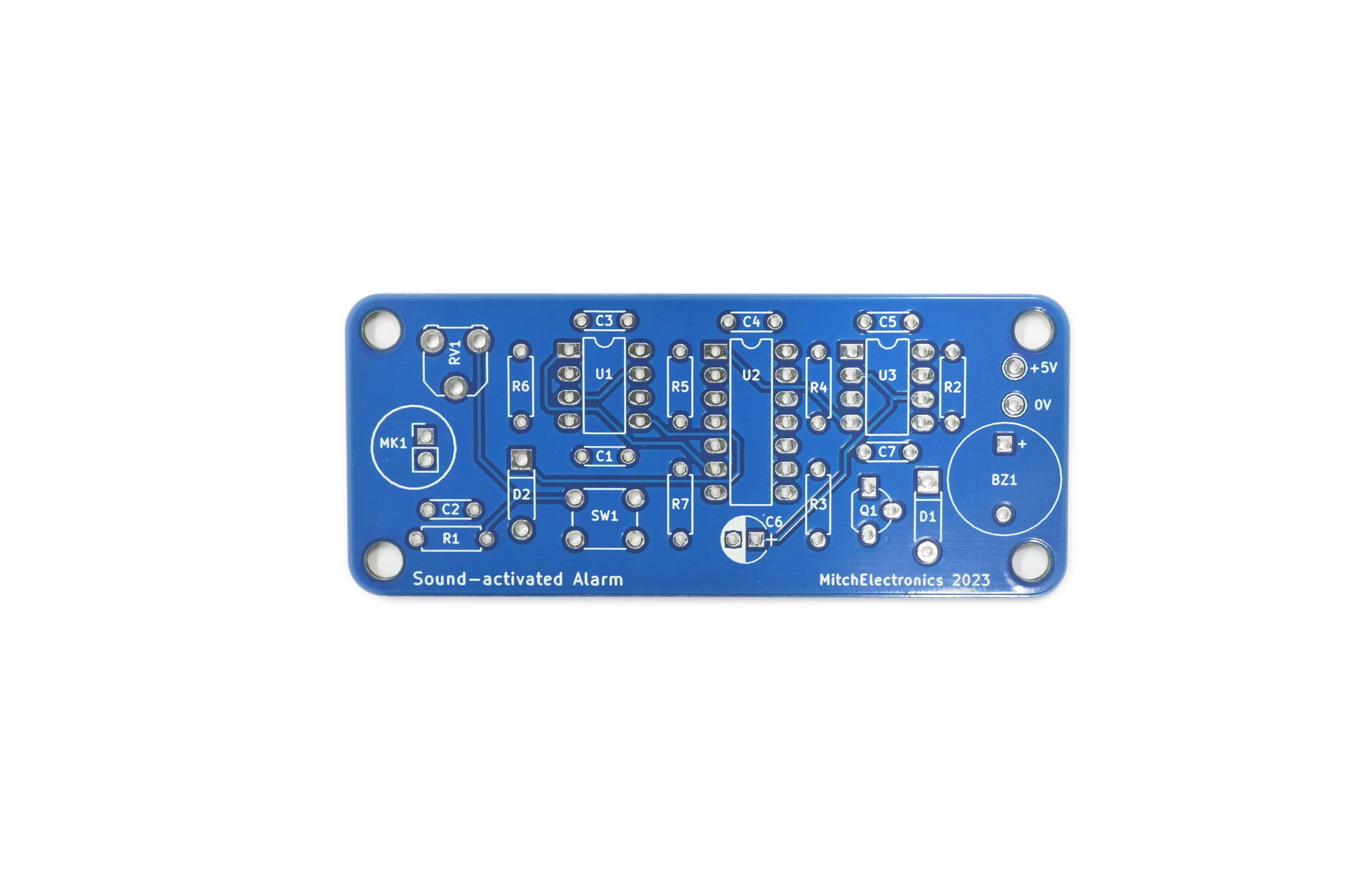
The PCB silkscreen and component references should be checked against the component list before soldering each part.
Before applying power
- Check every component against its PCB reference.
- Confirm the orientation of all polarised components and ICs.
- Inspect for solder bridges, unsoldered pads and clipped leads that could cause a short.
- Check that no loose wire or solder debris remains on the board.
Build with confidence
Construction tips
Recommended build order
A reliable way to assemble Sound Alarm Kit is to work from the lowest-profile components to the tallest. This keeps the PCB easy to access while you solder.
- Fit resistors, links and other low-profile components first.
- Fit small capacitors and diodes, checking polarity where applicable.
- Fit IC sockets and small semiconductors, observing the orientation markings.
- Fit larger capacitors, potentiometers, switches and other controls.
- Fit LEDs, connectors and the remaining taller components.
- Insert socketed ICs only after soldering around the socket is complete.
- Inspect every joint and check for solder bridges before applying power.
Electronics construction guidance
If you are new to kit construction, use the Soldering Guide alongside these instructions. Identify each component before fitting it and compare its reference with the component list and PCB silkscreen.
When it does not work
Troubleshooting
Nothing happens when power is applied
- Confirm the supply is connected to the correct input and with the correct polarity.
- Check that ICs, diodes, LEDs, transistors and electrolytic capacitors are fitted in the correct orientation.
- Compare component values and positions against the component list and PCB reference.
- Inspect for missed joints, dry joints and accidental solder bridges.
The circuit powers up but does not behave as expected
This kit is intended for sound-activated alarm. If the output is stuck, unstable or outside the expected behaviour, use the schematic to trace the circuit a stage at a time rather than replacing several parts at once.
Check the components around the part of the circuit responsible for the output or timing first. A misplaced resistor, reversed semiconductor or poor connection can allow a circuit to power up while preventing it from operating correctly.
The circuit works intermittently
Intermittent behaviour is often caused by a marginal solder joint, a loose connector or a component lead that has not been fully soldered. Gently inspect the board with power removed and reflow any joint that looks dull, cracked or incomplete.
If the fault remains, compare the assembled board with the schematic and PCB reference one connection at a time.
Ready to test and experiment?
Feeling brave? Consider using different resistors and capacitors on the 555 oscillator Move the reset switch externally to the board so only a remote operator can reset the alarm
Once the board is working, compare its behaviour with the schematic and the explanation above. Try changing only one input, control or permitted component value at a time so you can clearly see what effect that change has on the circuit.