
Interactive electronics resource
Siren LFO Synthesiser Instructions
Build, understand and experiment with the Siren LFO Synthesiser. This resource brings the original kit material into the current MitchElectronics format with the schematic, circuit explanation, component and PCB information, construction guidance, troubleshooting and practical ideas where available.
Introduction
Pre-learning – The VCO Kit
Before you learn how the LFO Siren Synthesiser works, it is best to first get the VCO kit and learn how that works, as this LFO Siren Synthesiser kit has two VCOs inside it, which make up the core of this project.
What is the LFO Siren Synthesiser?
The MitchElectronics LFO Siren Kit is a two-stage LFO/VCO circuit that can be used to produce a wide range of tones and patterns including ambulances, fire trucks, warning systems, octave pulses, and much more.
However, there is much more to this kit that strange and annoying sounds, and in this kit, you will not only learn how it works, but why.
What is an LFO?
A Low Frequency Oscillator, or LFO, is a special oscillator that focuses on the generation of low frequency oscillations. While oscillators found in musical instruments can be between 50Hz and 44kHz, those found in LFOs will often be less than 1Hz. But what benefits does a LFO provide, and how are they used in the music industry?
Depending on the genre of music you like, you may at times hear sudden variations in a tone, such as a rising note, a wobble, or in the case of Dub Step, the wah-wah of a screeching noise. All of these effects are controlled by LFOs, such as the rate of wobble, the pitch of the note, or the gating of it.
How does it differ to the VCO kit?
The MitchElectronics VCO kit is different in that it consists of just a single voltage controlled oscillator stage whose frequency can vary between 20Hz and 40kHz. While this allows it to produce a tone, it isn’t very useful for producing slow changing signals. Furthermore, only the LFO can produce a tone AND change its nature, whereas the VCO can only produce a fixed tone for a fixed input voltage.
Thus, the VCO kit would be used in conjunction with a. keyboard or other musical voltage source, while the LFO Siren is an entire instrument in its own right.
Schematic
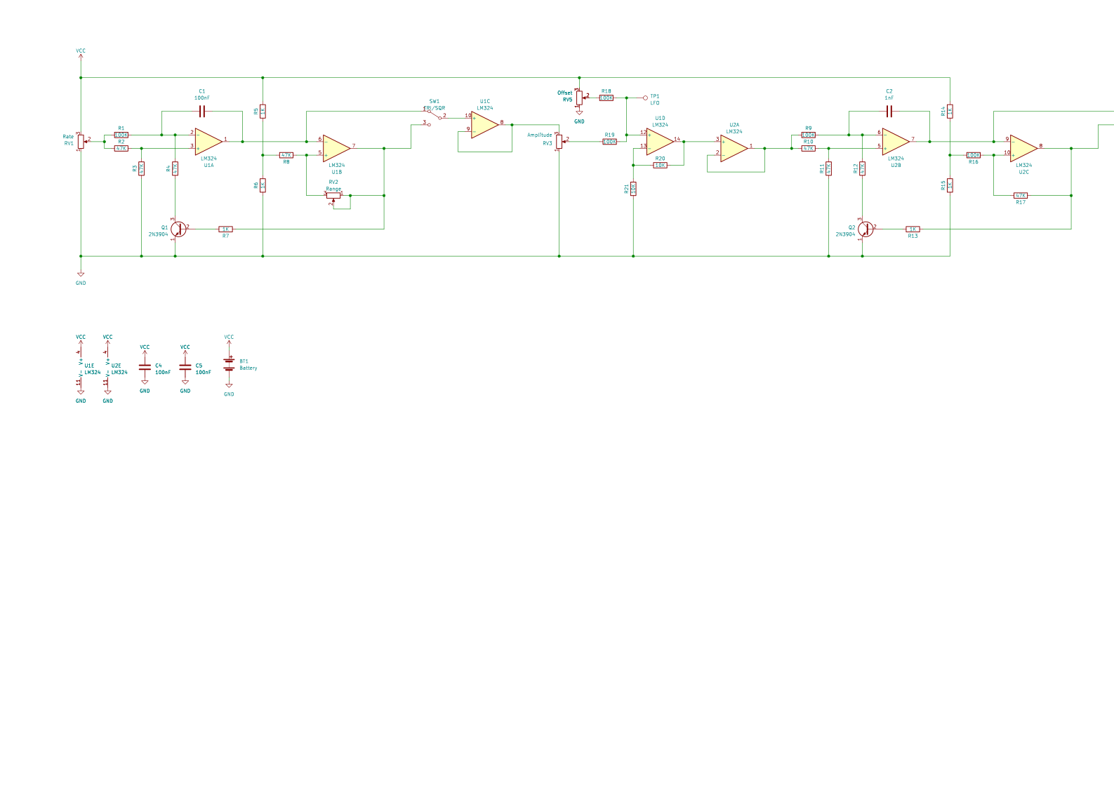
How the Siren LFO Synthesiser works
Before diving into the exciting world that is the LFO Siren Kit, it is a good idea to get the VCO kit and look through the instructions which can be found here, as this will explain how VCOs work (we will not be covering that here).
There are several different parts that make the Siren LFO work, but the four most important are the first VCO (acting as an LFO), the adjustment potentiometers, the second tone VCO, and the selection switches.
Starting with the first and most important part, the first VCO (made from U1A and U1B), is the exact same circuit as that found in the VCO kit, with the exception that the input voltage to the VCO is controlled by the potentiometer RV1 instead of an external voltage. This potentiometer is used to change the output frequency of the VCO, but because of the large size of C1, the frequency of oscillation is very slow (all the way from 0Hz to 1kHz), thus making it an LFO. A second potentiometer, RV2, is used to control the output voltage range of the LFO which effectively increases / reduces the amplitude of the output.
Once the LF waveform has been produced, both the triangular and square wave from the oscillator is fed into a selector switch, so you can decide between a rise and fall in output tone, or a sudden switch between two tones. This signal is then fed into a unity gain buffer (U1C), and this output is then fed into a potentiometer RV3, which determines the amplitude of the final output from the whole LFO stage.
This varied amplitude signal from the LFO stage is then combined with the output from another potentiometer RV5. This potentiometer is used to add an offset to the LFO output, so its centre oscillation frequency can be varied. This offset is also key to setting the main tone for the second VCO, meaning that if the first stage LFO was turned off, the offset potentiometer would force the second VCO to produce a specific tone (adjusting the potentiometer will change this tone).
The LFO and offset are added together using the summation amplifier U1D, and the output of this summation stage is then buffered with a unity gain buffer U2A. By using the buffer, we ensure that the second VCO stage doesn’t affect the performance of our LFO circuit.
The final stage that is used to generate tones is the second VCO, made up of U2A and U2B. Because of the much smaller capacitor (C2), this stage has a much higher frequency, allowing for most audible tones. The input to this VCO is the combination of all the previous stages, meaning that making changes to any of the potentiometers will change the tone,
The final “final” stage is a simple push pull amplifier (Q3 and Q4) which amplifies the output of the VCO so that it can drive a small external speaker.
Try it yourself
Circuit simulation
What you need
Component List
| Component | Quantity | PCB Reference |
|---|---|---|
| 14 DIP Sockets | 2 | U1, U2 |
| LM324 | 2 | U1, U2 |
| 1nF Capacitor | 1 | C2 |
| 100nF Capacitor | 3 | C1, C4, C5 |
| 100uF Capacitor | 1 | C3 |
| 1K Resistor | 6 | R5, R6, R7, R13, R14, R15 |
| 10K Resistor | 2 | R20, R21 |
| 47K resistor | 8 | R2, R3, R4, R8, R10, R11, R12, R17 |
| 100K resistor | 5 | R1, R9, R16, R18, R19 |
| 2N3904 | 3 | Q1, Q2, Q3 |
| 2N3906 | 1 | Q4 |
| 100K Linear Potentiometer | 4 | RV1 to RV5 |
| Slide Switch | 2 | SW1, SW2 |
| Red Wire | 1 | LS1 |
| Black Wire | 1 | LS1, GND |
| Speaker | 1 | LS1 |
| PP3 Battery Connector | 1 | BT1 |
| Siren PCB | 1 | — |
Inspect the board
Interactive BOM
Board reference
PCB & assembly
The PCB silkscreen and component references should be checked against the component list before soldering each part.
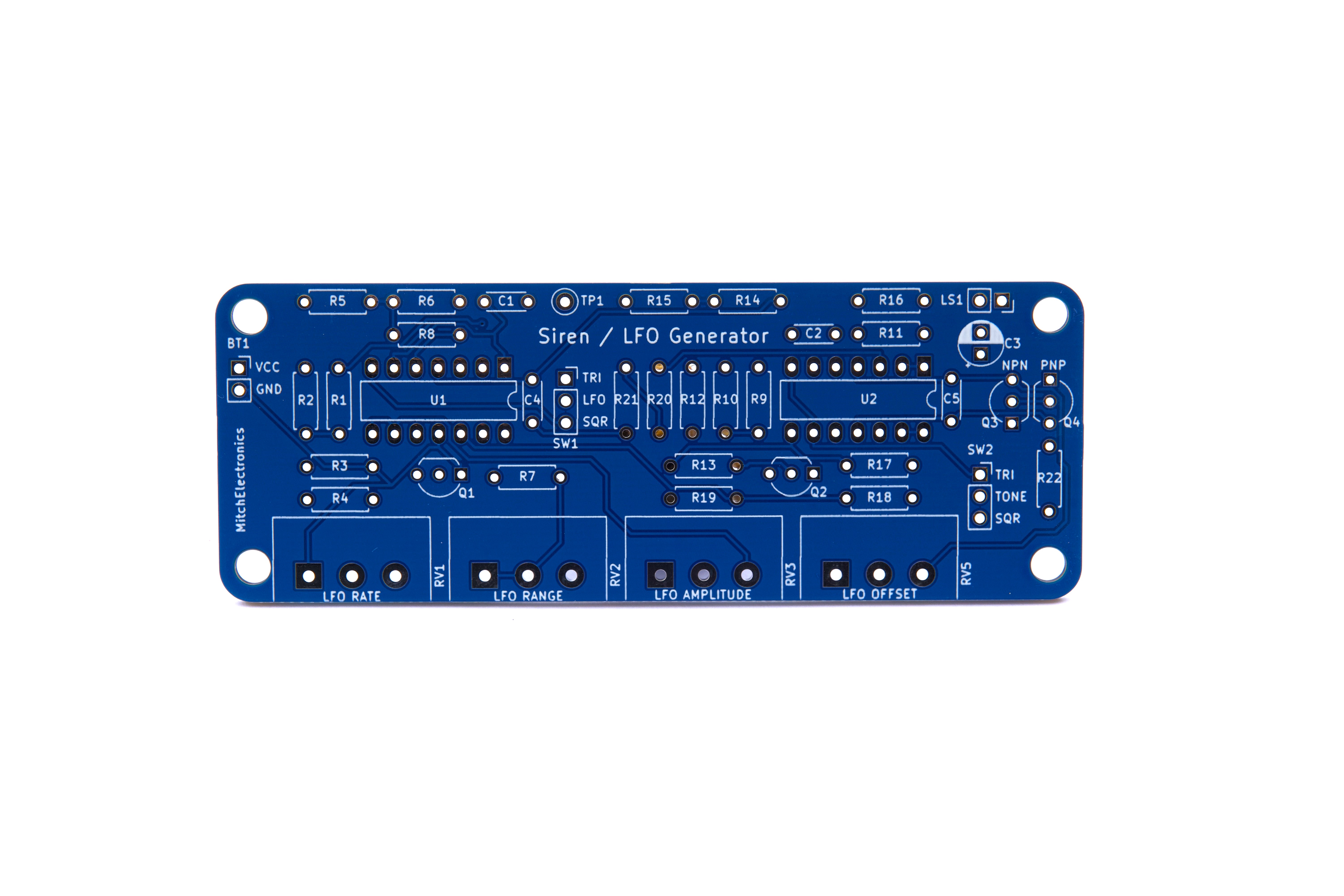
Before applying power
- Check every component against its PCB reference.
- Confirm the orientation of all polarised components and ICs.
- Inspect for solder bridges, unsoldered pads and clipped leads that could cause a short.
- Check that no loose wire or solder debris remains on the board.
Build with confidence
Construction tips
Recommended build order
A reliable way to assemble Siren LFO Synthesiser is to work from the lowest-profile components to the tallest. This keeps the PCB easy to access while you solder.
- Fit resistors, links and other low-profile components first.
- Fit small capacitors and diodes, checking polarity where applicable.
- Fit IC sockets and small semiconductors, observing the orientation markings.
- Fit larger capacitors, potentiometers, switches and other controls.
- Fit LEDs, connectors and the remaining taller components.
- Insert socketed ICs only after soldering around the socket is complete.
- Inspect every joint and check for solder bridges before applying power.
Electronics construction guidance
If you are new to kit construction, use the Soldering Guide alongside these instructions. Identify each component before fitting it and compare its reference with the component list and PCB silkscreen.
When it does not work
Troubleshooting
Nothing happens when power is applied
- Confirm the supply is connected to the correct input and with the correct polarity.
- Check that ICs, diodes, LEDs, transistors and electrolytic capacitors are fitted in the correct orientation.
- Compare component values and positions against the component list and PCB reference.
- Inspect for missed joints, dry joints and accidental solder bridges.
The circuit powers up but does not behave as expected
This kit is intended for low-frequency siren synthesiser. If the output is stuck, unstable or outside the expected behaviour, use the schematic to trace the circuit a stage at a time rather than replacing several parts at once.
Check the components around the part of the circuit responsible for the output or timing first. A misplaced resistor, reversed semiconductor or poor connection can allow a circuit to power up while preventing it from operating correctly.
The circuit works intermittently
Intermittent behaviour is often caused by a marginal solder joint, a loose connector or a component lead that has not been fully soldered. Gently inspect the board with power removed and reflow any joint that looks dull, cracked or incomplete.
If the fault remains, compare the assembled board with the schematic and PCB reference one connection at a time.
Ready to test and experiment?
Once the board is working, compare its behaviour with the schematic and the explanation above. Try changing only one input, control or permitted component value at a time so you can clearly see what effect that change has on the circuit.