
Interactive electronics resource
Simple Power Module SMD Instructions
Build, understand and experiment with the Simple Power Module SMD. This resource brings the original kit material into the current MitchElectronics format with the schematic, circuit explanation, component and PCB information, construction guidance, troubleshooting and practical ideas where available.
Introduction
What is the Simple Power Module SMD Trainer?
The Simple Power Module SMD Trainer kit is a module that provides two regulated output voltages from a single input voltage. These two voltages are 5V and 3.3V, and can be used to power most maker circuits including microcontrollers, sensors, shields, and add-ons. Furthermore, each regulated output has its own fuse, which protects the regulators and the circuit being powered.
As the aim of this kit is to introduce you to SMD soldering, the theory behind the circuit will not be covered here.
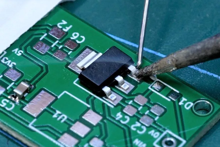
What can you do with the Simple Power Module SMD Trainer?
Besides the obvious use of SMD training, the Simple Power Module can be used in many different projects. For example, the Simple Power Module SMD can be used for converting a 9V battery into a 3.3V source suitable for a Raspberry Pi Pico microcontroller. The module could also be used for providing 5V to a micro servo and a 3.3V source for a sensor.
The spacing between the input and output have been designed to fit across a breadboard, meaning that this module is breadboard friendly. As such, you can use this module with breadboard designs, thereby allowing for reuse and modification.
Schematic
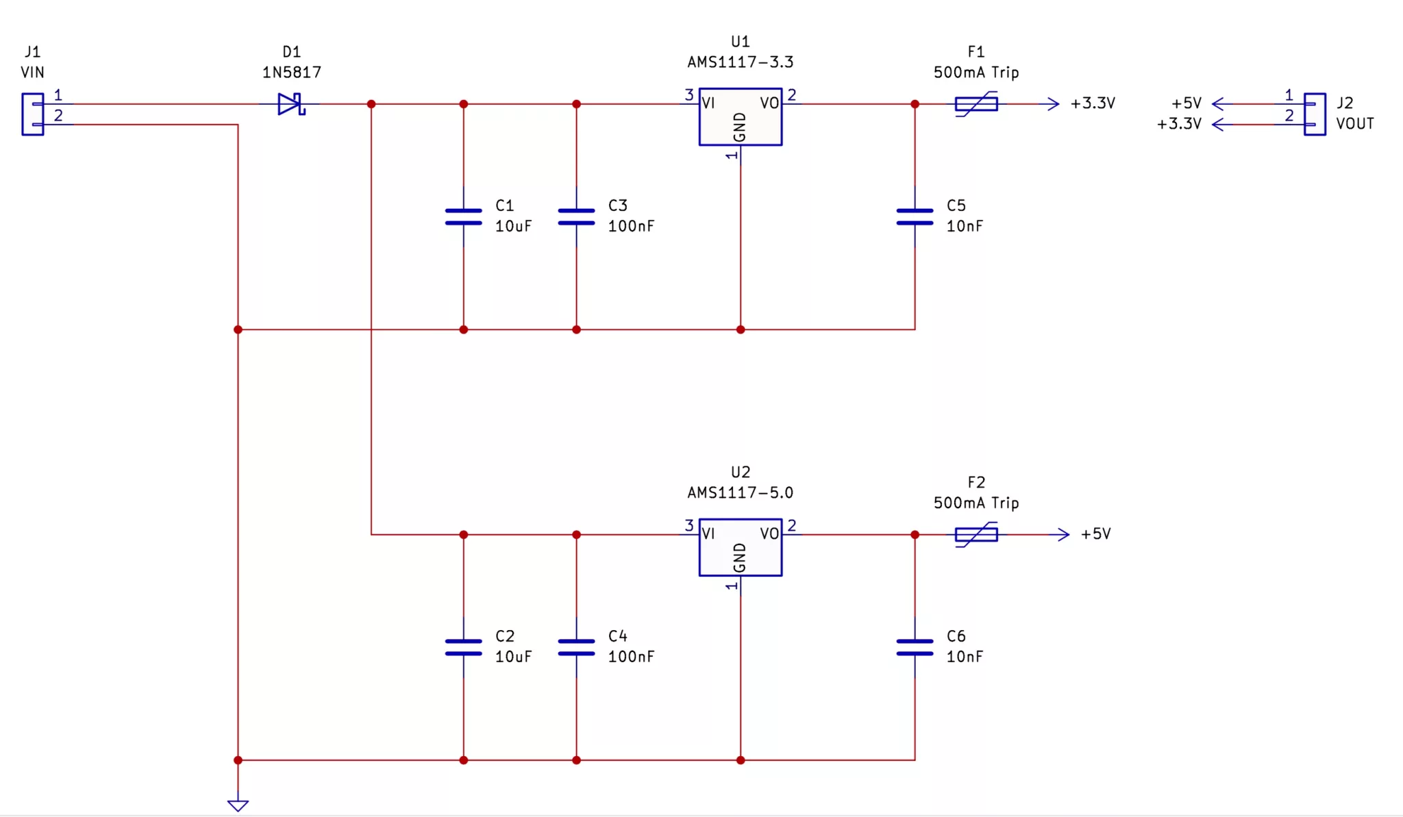
Try it yourself
Circuit simulation
What you need
Component List
| Component | Quantity | PCB Reference |
|---|---|---|
| AMS1117 3.3V | 1 | U1 |
| AMS1117 5V | 1 | U2 |
| 10µF Capacitor | 2 | C1, C2 |
| 100nF Capacitor | 2 | C3, C4 |
| 10nF Capacitor | 2 | C5, C6 |
| Poly Fuse | 2 | F1, F2 |
| 1N5817 Diode | 1 | D1 |
| 4 Way Pin Header | 1 | J1, J2 |
| Simple Power Module SMD PCB | 1 | — |
Inspect the board
Interactive BOM
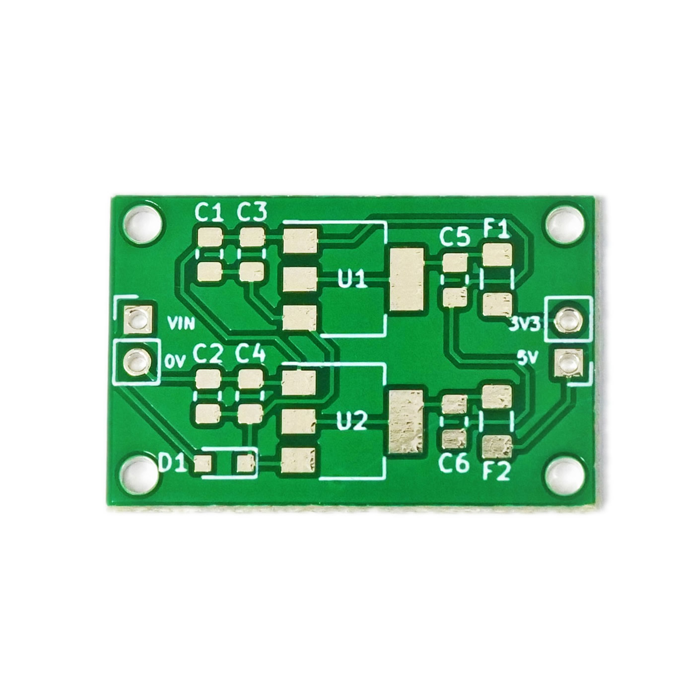
Board reference
PCB & assembly
The PCB silkscreen and component references should be checked against the component list before soldering each part.
Before applying power
- Check every component against its PCB reference.
- Confirm the orientation of all polarised components and ICs.
- Inspect for solder bridges, unsoldered pads and clipped leads that could cause a short.
- Check that no loose wire or solder debris remains on the board.
Build with confidence
Construction tips
Recommended build approach
Simple Power Module SMD uses surface-mount components, so work methodically and inspect each joint as you go.
- Check the component values and package markings before soldering.
- Start with the smallest passive components and work towards larger devices and connectors.
- For multi-pin devices, align the package carefully and tack one pad first; correct the alignment before soldering the remaining pins.
- Use only enough solder to form a clean joint and watch closely for bridges between adjacent pads.
- Observe the orientation marks on diodes, LEDs, ICs and any other polarised components.
- Inspect the board under good light or magnification before applying power.
SMD soldering guidance
If you are new to surface-mount assembly, use the SMD Soldering Guide alongside these instructions. Keeping the tip clean, using flux where appropriate and checking alignment frequently makes the build much easier.
When it does not work
Troubleshooting
Nothing happens when power is applied
- Confirm the supply is connected to the correct input and with the correct polarity.
- Check that ICs, diodes, LEDs, transistors and electrolytic capacitors are fitted in the correct orientation.
- Compare component values and positions against the component list and PCB reference.
- Inspect for missed joints, dry joints and accidental solder bridges.
- Closely inspect fine-pitch and adjacent SMD pads for solder bridges or unsoldered ends.
The circuit powers up but does not behave as expected
This kit is intended for smd power module trainer. If the output is stuck, unstable or outside the expected behaviour, use the schematic to trace the circuit a stage at a time rather than replacing several parts at once.
Check the components around the part of the circuit responsible for the output or timing first. A misplaced resistor, reversed semiconductor or poor connection can allow a circuit to power up while preventing it from operating correctly.
The circuit works intermittently
Intermittent behaviour is often caused by a marginal solder joint, a loose connector or a component lead that has not been fully soldered. Gently inspect the board with power removed and reflow any joint that looks dull, cracked or incomplete.
If the fault remains, compare the assembled board with the schematic and PCB reference one connection at a time.
Ready to test and experiment?
To help keep the board stable when soldering, you can download a free STL model of a basic jig that can be 3D printed with all common 3D printers. Watch out for the mounting hole pins as they may be vulnerable to snapping if using a low infill density, low wall thickness, or thick layer heights. Additionally, do not use hot air to solder the PCB when using the jig as you will melt the jig. Coming Soon...
Once the board is working, compare its behaviour with the schematic and the explanation above. Try changing only one input, control or permitted component value at a time so you can clearly see what effect that change has on the circuit.