
Interactive electronics resource
Micro Audio Amp Kit Instructions
Build, understand and experiment with the Micro Audio Amp Kit. This resource brings the original kit material into the current MitchElectronics format with the schematic, circuit explanation, component and PCB information, construction guidance, troubleshooting and practical ideas where available.
Introduction
The Micro Audio Amp is a miniature audio amplifier based on the LM358 operational amplifier and uses a secondary push-pull amplifier for driving external speakers. Audio signals can be fed into the AUDIOIN pin, and the potentiometer provides a variable gain control.
While the output of this kit is directly connected to a small speaker for testing purposes, it can easily be modified with an external connector for use with larger speakers (such as RCA connectors). This kit can also be connected to other MitchElectronics audio projects, such as the 555 Astable and the 555 Synth Punk, for amplification purposes.
Schematic
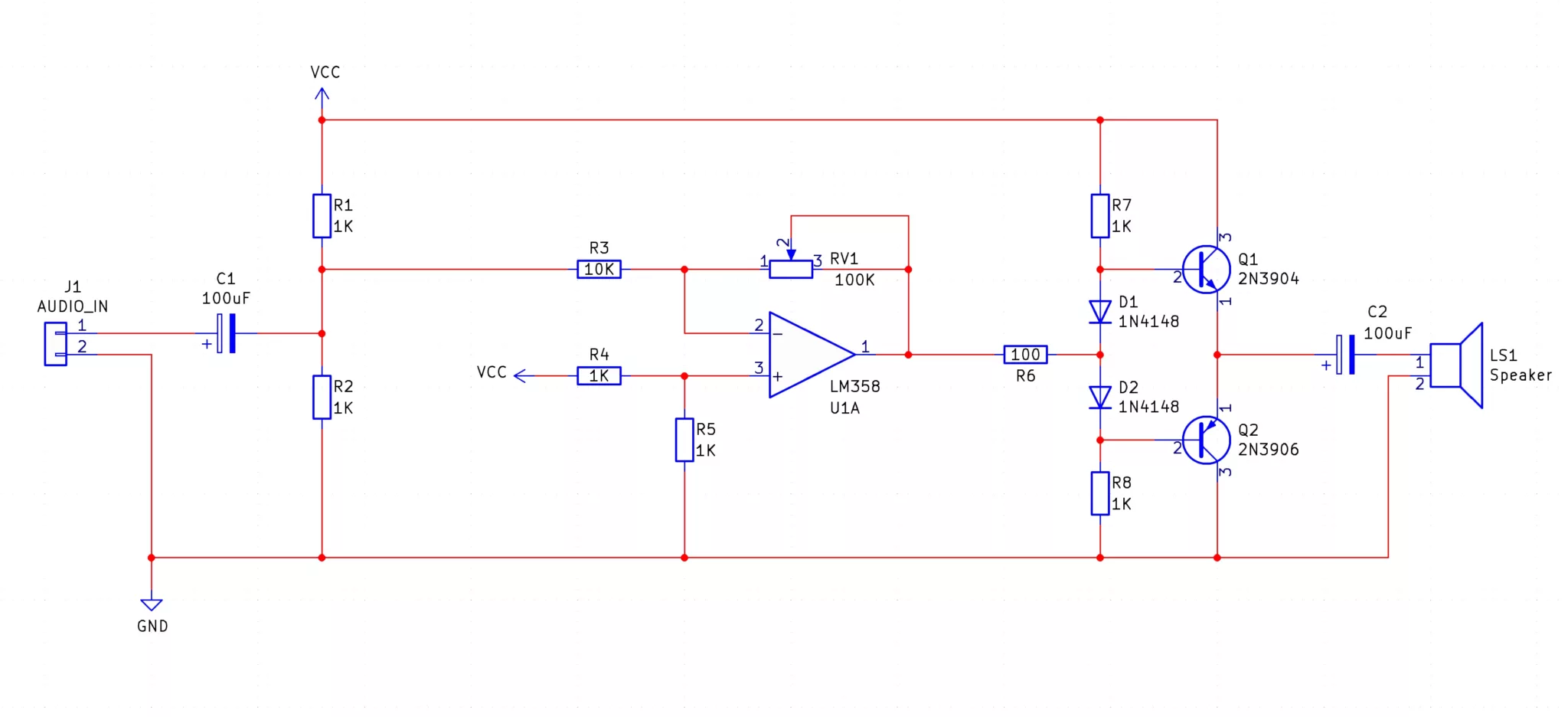
SCHEMATIC (Block diagram)
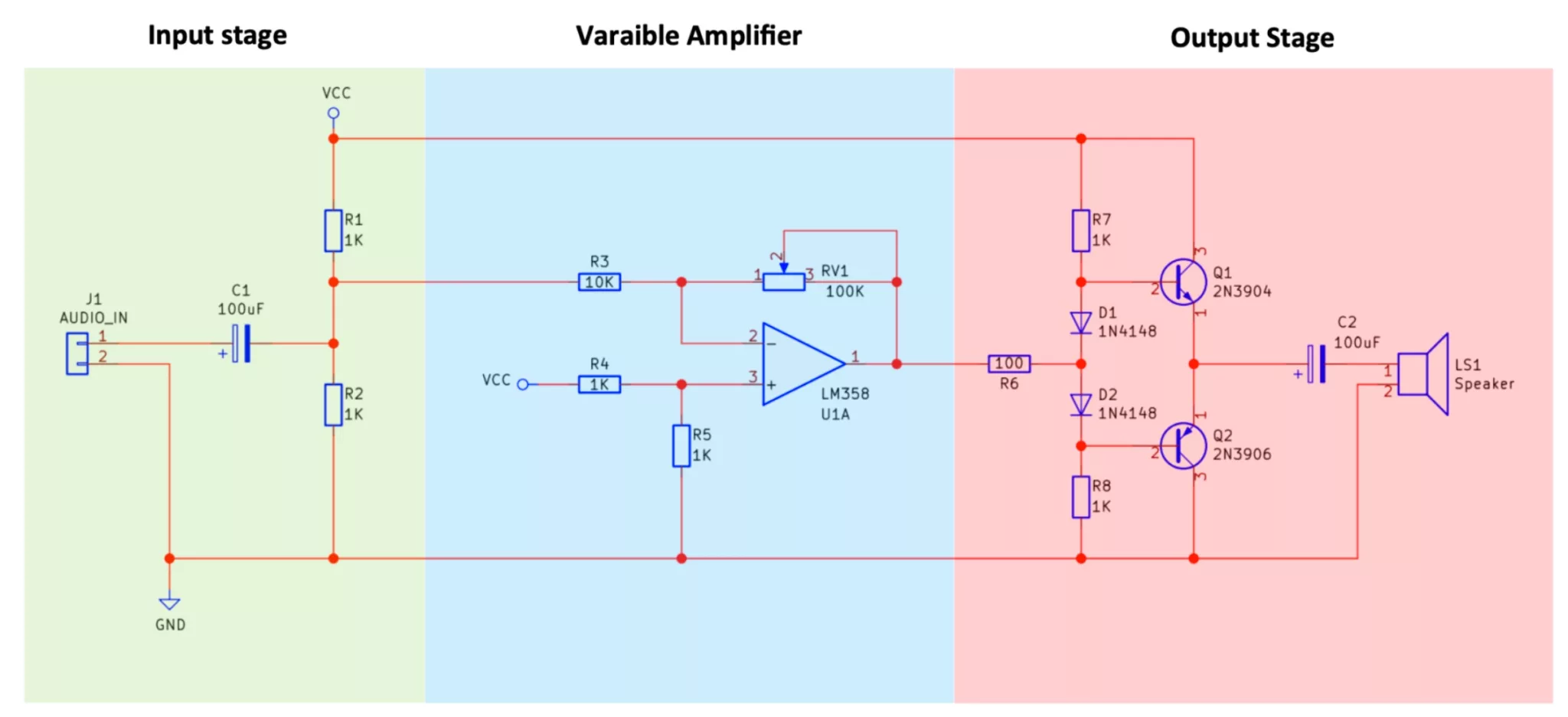
How does the micro audio amp work?
The Micro Audio Amp is a small audio amplifier that can be used to amplify small audio signals commonly found in audio ports on computers, laptops, and phones. While the signals from these ports can directly drive small speakers such as headphones it is nowhere near powerful enough to drive larger speakers which allows for multiple people to listen. If a larger speaker is to be used then an amplifier that can increase the power capability of the signal is required and this is exactly what this kit does!
Stage 1 - Coupling and DC Offset
The first stage is the input stage which takes an audio signal and performs two tasks. The first task is accomplished by C1 which is a coupling capacitor. The purpose of this capacitor is to remove any DC signal that may be present from the incoming audio signals. The second task of the input stage is to add a constant VCC/2 DC bias to the audio signal. But why do we add this bias?
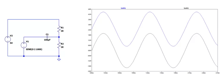
If you look at the op-amp U1 you can see that it is powered by VCC and GND only, and therefore the op-amp U1 is operating from a single rail supply. Since the op-amp is operating from a single rail supply it cannot amplify negative signals and therefore we need to ensure that all signals to the op-amp stage are positive. As the incoming audio signals are coupled they will have a negative portion to their waveform so to preserve this, we add a small DC bias which shifts the audio signal and makes it all positive. The graph below shows how a sine wave (black) which oscillates about 0V and has a negative component is shifted up to oscillate about 2.5V with no negative component remaining.
Stage 2 - Inverting Amplifier
The next stage in the audio amplifier is an inverting amplifier with a variable gain whose value is determined by the ratio of R3 to the potentiometer RV1. A typical inverting amplifier has its positive input (+) connected to ground but that only applies in dual-rail mode. Since we are operating in single-rail mode we have to instead connect this pin to VCC/2 which is done using a simple potential divider consisting of R4 and R5. The reason for using this voltage reference is because this is the same value that is added to our signal. This means that when our amplifier amplifies the audio input it will ignore the DC offset that we added.
Stage 3 - Push-Pull Amplifier
The last stage in the micro audio amp is the push-pull amplifier made up of Q1, Q2, D1, D2, R7, and R8. The resistor R6 is a series current limiting resistors that prevent the two transistors Q1 and Q2 from being damaged while the two diodes D1 and D2 remove the cross-over distortion that these types of push-pull amplifiers typically suffer from (you can read more about this online). While the op-amp U1 amplifies the incoming signal the op-amp itself cannot source much current and therefore cannot be used to directly drive a speaker.
To solve this problem, Q1 and Q2 are used which buffer the output signal from U1 but have a low output impedance. This means that the Q1 / Q2 amplifier stage can drive bigger loads and in this case, a small 8-ohm 1W speaker. The last stage of the circuit is a coupling capacitor C2 whose purpose is to remove any DC offset from our output signal.
Using the Micro Audio Amp
The micro audio amplifier demonstrates a simple audio amp and can be used to amplify audio signals from a range of sources. However, the speaker that is provided with the kit will not be very loud if used on its own and this is a problem that many makers face. The reason for this is that speakers, to be effective, need to be placed in an audio cavity (such as a speaker box). If, for example, the speaker supplied with this kit is placed on top of an empty drinks can with the speaker's face pointing towards the can opening, then the sound of the speaker is dramatically amplified.
Project ideas
Basic Synthesiser Amplifier
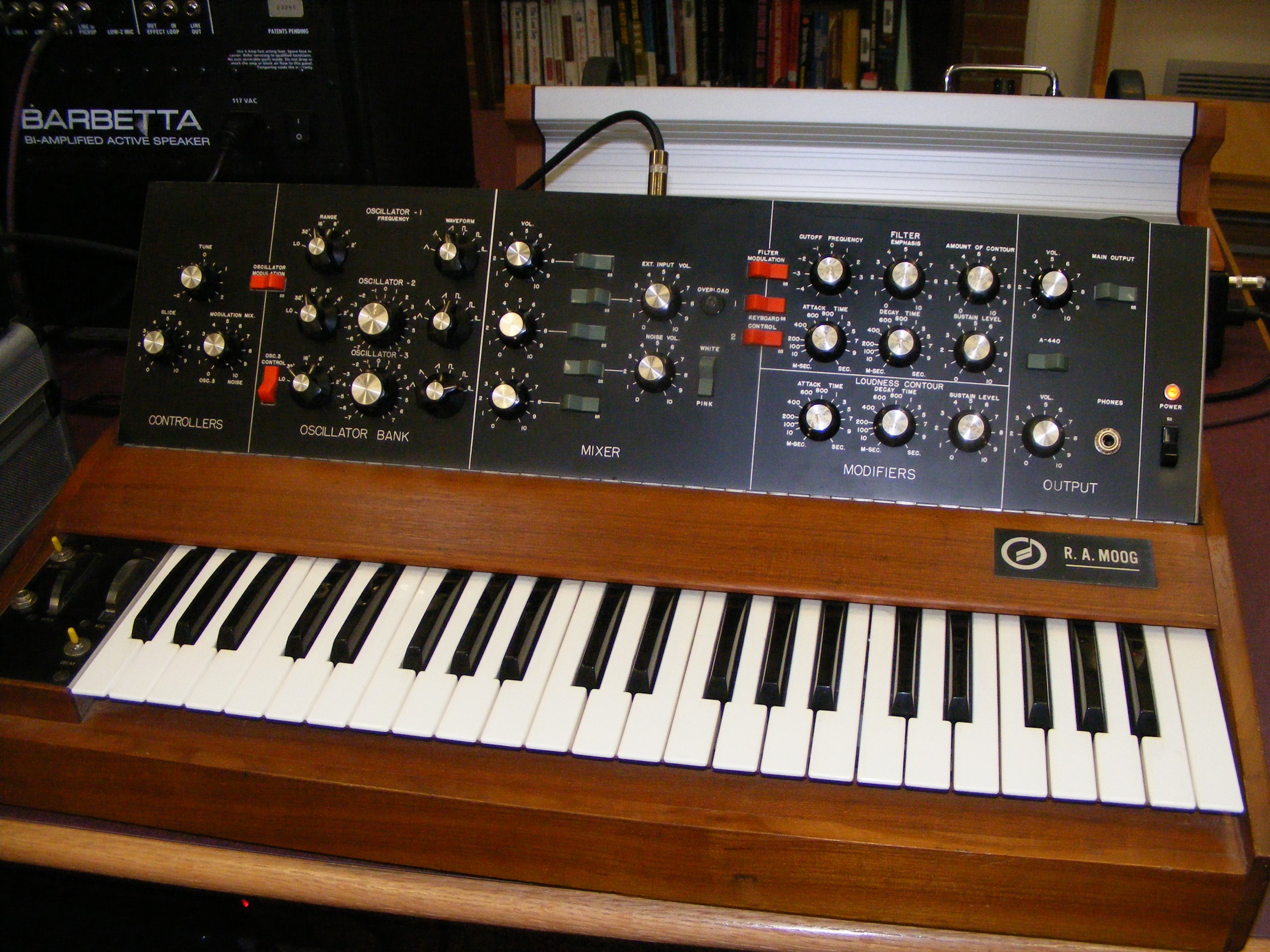
While this kit alone doesn't produce tones, it can be used with other circuits that do! For example, the 555 Synth Punk, the Voltage Controlled Oscillator, and the 555 Astable Kit all produce audible tones which can be fed into the Micro Audio Amp to be amplified onto a speaker.
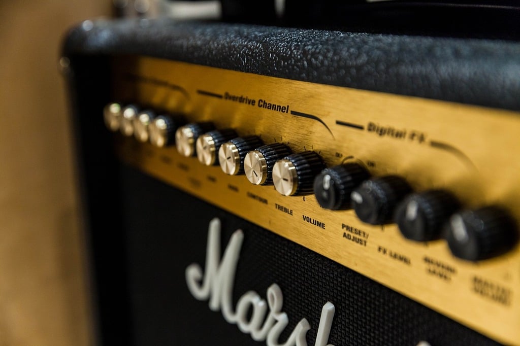
This also applies to musical instruments such as electric guitars, keyboards, and drum kits that have audio output connections.
Microphone Amplifier
Generally speaking, microphones cannot be directly connected to speakers as the signal they produce is far too small. In these cases, the Micro Audio Amp can be used to amplify these small signals so they can drive larger speakers. This is especially useful for microphones that are un-driven, and such amplifiers are typically referred to as pre-amps.
Try it yourself
Circuit simulation
What you need
Component List
| Component | Quantity | PCB Reference |
|---|---|---|
| 8 DIP Socket | 1 | U1 |
| LM358 | 1 | U1 |
| 100Ω Resistor | 1 | R6 |
| 1KΩ Resistor | 6 | R1, R2, R4, R5, R7, R8 |
| 10KΩ Resistor | 1 | — |
| 100KΩ Potentiometer | 1 | R3 |
| 100µF Capacitor | 2 | C1, C2 |
| 1N4148 Diode | 2 | D1, D2 |
| 2N3904 BJT | 1 | Q1 |
| 2N3906 BJT | 1 | Q2 |
| Speaker | 1 | LS1 |
| Red Wire | 2 | VCC, LS1 |
| Black Wire | 2 | GND, LS1 |
| Green Wire | 1 | AUDIO IN |
| Blue Wire | 1 | AUDIO OUT |
| Micro Audio Amp PCB | 1 | — |
Inspect the board
Interactive BOM
Board reference
PCB & assembly
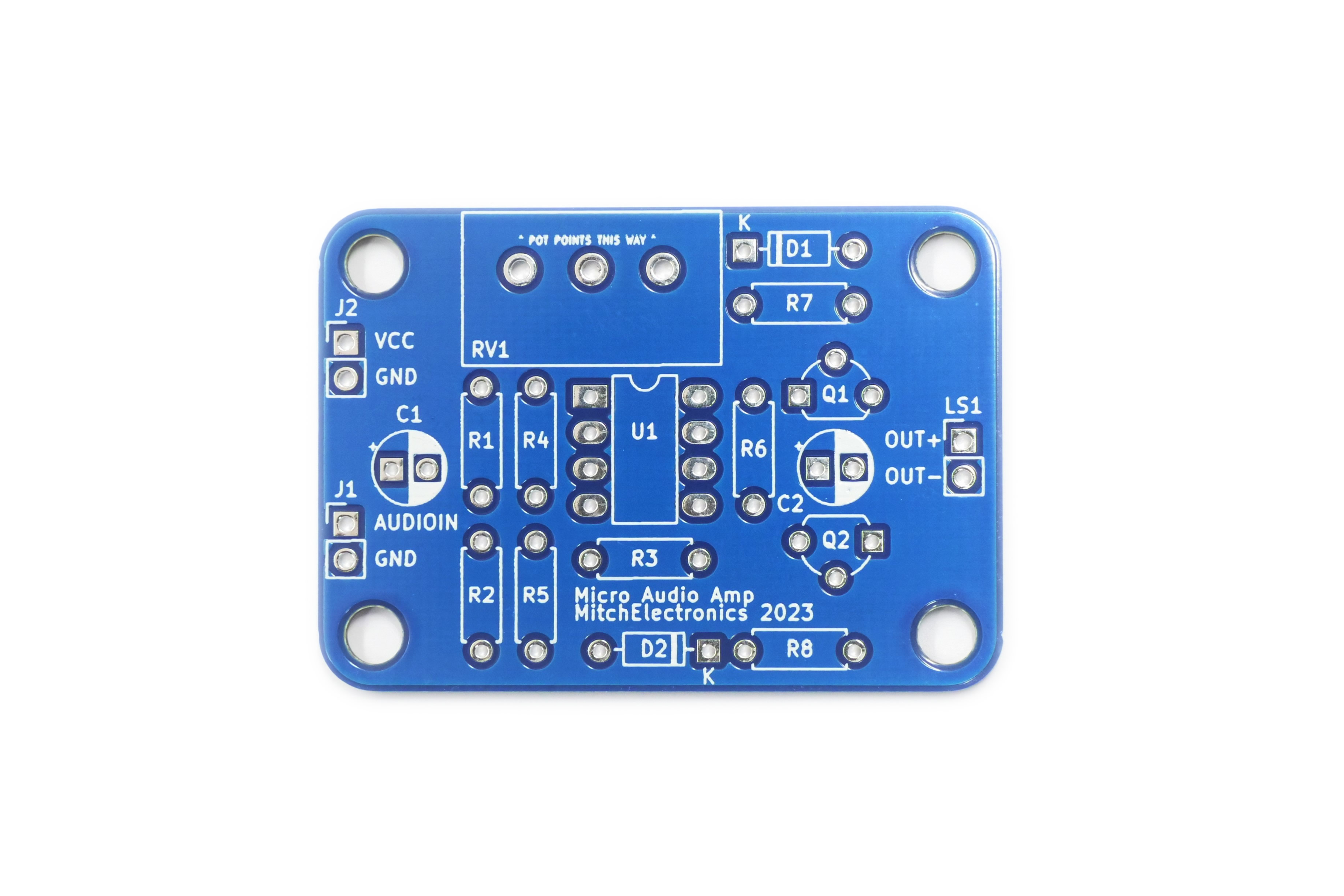
The PCB silkscreen and component references should be checked against the component list before soldering each part.
Before applying power
- Check every component against its PCB reference.
- Confirm the orientation of all polarised components and ICs.
- Inspect for solder bridges, unsoldered pads and clipped leads that could cause a short.
- Check that no loose wire or solder debris remains on the board.
Build with confidence
Construction tips
Recommended build order
A reliable way to assemble Micro Audio Amp Kit is to work from the lowest-profile components to the tallest. This keeps the PCB easy to access while you solder.
- Fit resistors, links and other low-profile components first.
- Fit small capacitors and diodes, checking polarity where applicable.
- Fit IC sockets and small semiconductors, observing the orientation markings.
- Fit larger capacitors, potentiometers, switches and other controls.
- Fit LEDs, connectors and the remaining taller components.
- Insert socketed ICs only after soldering around the socket is complete.
- Inspect every joint and check for solder bridges before applying power.
Electronics construction guidance
If you are new to kit construction, use the Soldering Guide alongside these instructions. Identify each component before fitting it and compare its reference with the component list and PCB silkscreen.
When it does not work
Troubleshooting
Nothing happens when power is applied
- Confirm the supply is connected to the correct input and with the correct polarity.
- Check that ICs, diodes, LEDs, transistors and electrolytic capacitors are fitted in the correct orientation.
- Compare component values and positions against the component list and PCB reference.
- Inspect for missed joints, dry joints and accidental solder bridges.
The circuit powers up but does not behave as expected
This kit is intended for compact audio amplifier. If the output is stuck, unstable or outside the expected behaviour, use the schematic to trace the circuit a stage at a time rather than replacing several parts at once.
Check the components around the part of the circuit responsible for the output or timing first. A misplaced resistor, reversed semiconductor or poor connection can allow a circuit to power up while preventing it from operating correctly.
The circuit works intermittently
Intermittent behaviour is often caused by a marginal solder joint, a loose connector or a component lead that has not been fully soldered. Gently inspect the board with power removed and reflow any joint that looks dull, cracked or incomplete.
If the fault remains, compare the assembled board with the schematic and PCB reference one connection at a time.
Ready to test and experiment?
Feeling brave? Consider using different resistors and capacitors
Once the board is working, compare its behaviour with the schematic and the explanation above. Try changing only one input, control or permitted component value at a time so you can clearly see what effect that change has on the circuit.