
Interactive electronics resource
IR Sense Kit Instructions
Build, understand and experiment with the IR Sense Kit. This resource brings the original kit material into the current MitchElectronics format with the schematic, circuit explanation, component and PCB information, construction guidance, troubleshooting and practical ideas where available.
Introduction
What is the SENSE range?
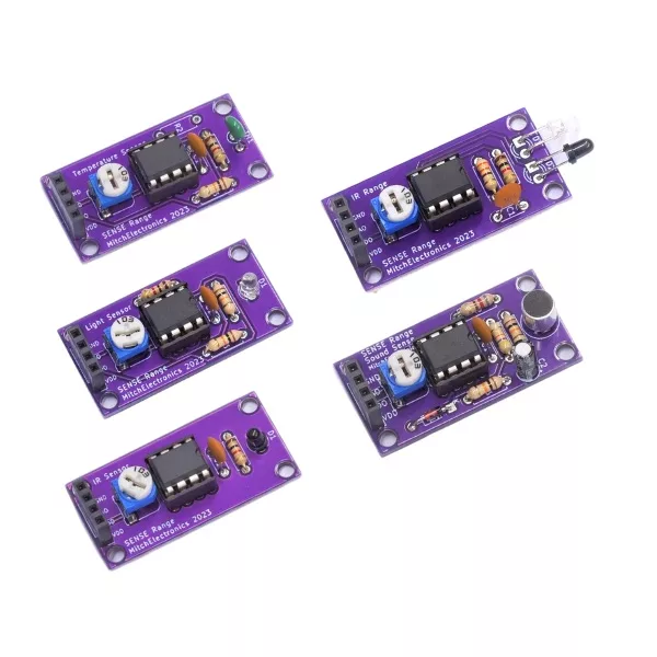
The SENSE Range are electronic kits that let you build your own module with sensing capabilities. Each module has the exact same dimensions, pin-out, and hole location so that modules can be interchanged depending on what needs detecting. For example, the Sound Sense is capable of detecting sound, while the Temp Sense uses a thermistor to detect the ambient temperature.
Unlike other sensing modules on the market, the simplicity of the MitchElectronics Sense Range makes them easy to modify, use in other circuits, and build. At the same time, the standardised 40mm x 20mm dimension is very easy to work with when creating enclosures and mounting a Sense board.
What is the standard pin-out for the SENSE range?
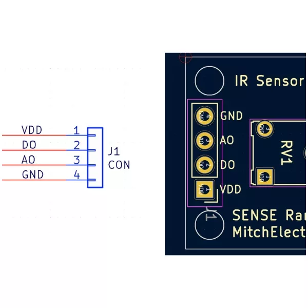
To make using the Sense Range as easy as possible, all Sense kits have a four pin connector that is identical for each device. Two of these pins are for providing power (VCC and 0V), and the other two are one digital output (that switches between VCC and 0V), and analogue output, which varies depending on the signal being sensed. For example, the Sound Sense produces an analogue signal whose amplitude increases with sound volume, while the Temp Sense produces a voltage that directly relates to temperature.
What is the standard dimension of the SENSE range?
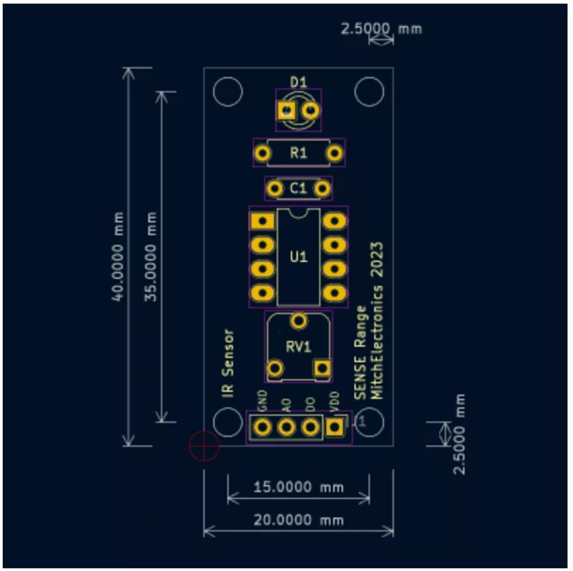
To make sure that using the Sense Range is as simple as possible, all dimensions, hole sizes, and positions are identical across all modules. By doing so, modules can be swapped around without needing to change enclosures, screws, or mountings. At the same time, this standardisation also allows for modules to be stacked in frames which can also be convenient
The standard size for all kits is 40mm x 20mm, M2 holes (2mm diameter), a hole separation of 35mm x 15mm, and a hole edge spacing of 2.5mm.
Schematic
How does the IR sense work?
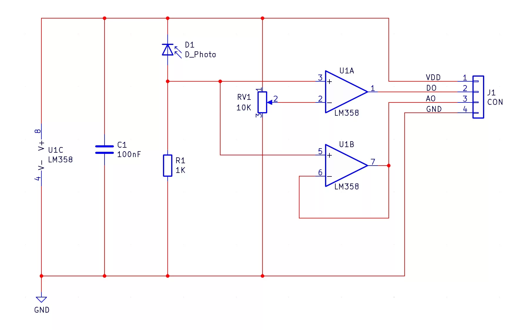
The IR Sense comprises of an IR detector diode (D1), a comparator (U1A), and a buffer (U1B).
You may notice that in the circuit, the IR diode is in reverse bias mode meaning that under normal circumstances, it doesn’t conduct any electricity. When IR light falls onto the IR diode, it causes the IR diode to become conductive, and the resistance of the IR diode depends on how much IR light is falling on it.
Because the resistor R1 is in series with the IR diode, the result is a potential divider whereby more light falling onto the IR diode reduces its resistance, thereby increasing the voltage across R1. The voltage across R1 is fed into both op-amps, U1A and U1B, which are configured as a comparator and a unity gain buffer respectively.
The comparator (U1A), has its negative input connected to a potentiometer, which produces a voltage between VCC and 0V depending on its position. If the voltage across R1 is greater than the voltage from the potentiometer the output of the comparator switches to VCC, indicating that the IR level is greater than the trigger level defined by the potentiometer. If the voltage across R1 is lower than the voltage from the potentiometer, the output of the comparator switches to 0V, indicating that the IR level is lower than the trigger level defined by the potentiometer. The output of the comparator is digital, and can be used to determine if the IR sensor has detected a minimum level of IR light.
The unity gain buffer is an op-amp that simply outputs whatever voltage is on its input, and this buffer allows external devices to read the voltage level across R1 without interfering with it. This output is analogue, and can be used to measure the amount of IR light falling onto the sensor.
Project ideas
TV Remote Detector
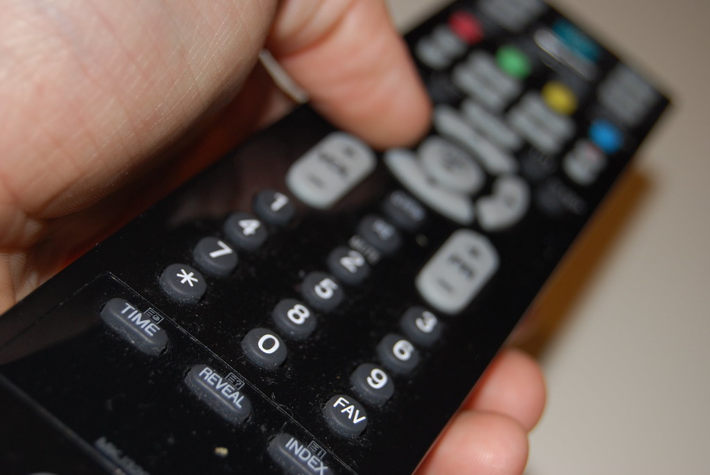
TV remotes use IR light to transmit data, and they can easily be picked up with this circuit. As such, this circuit can easily be used to decode IR signals from TV remotes if used with a microcontroller, or better, it can be used as a TV remote scanner that detects when someone is trying to change settings!
IR Barrier
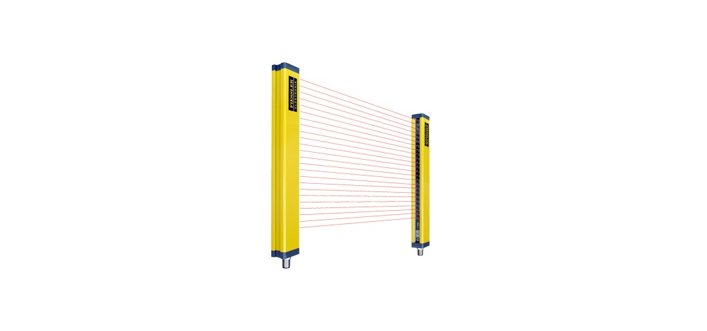
Sometimes, it can be important to protect a specific boundary, and this is commonly seen in industrial machinery where light curtains automatically shut down equipment if people cross them. The IR Range Sense can easily be used to create an invisible barrier that can detect if someone has passed. Furthermore, multiple IR Range Sense modules can be installed in parallel, and an open-source output on each module (using a single BJT) can trigger an alarm should any of the modules detect an object.
Fire Detector
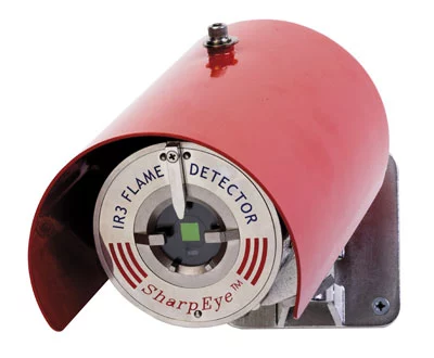
IR light is emitted by anything hot, and it turns out that fires emit extremely large amounts of IR light. As such, it is possible to create a flame detector using an IR sensor such as the one used in the IR Sense kit. The output comparator can be used to trigger an external alarm circuit when a flame has been detected, but please keep in mind that MitchElectronics kits are not suitable for creating life-saving equipment (experimentation only)!
Try it yourself
Circuit simulation
What you need
Component List
| Component | Quantity | PCB Reference |
|---|---|---|
| LM358 | 1 | U1 |
| 8 DIP Socket | 1 | U1 |
| IR Sensor | 1 | D1 |
| 1KΩ Resistor | 1 | R1 |
| 100nF Capacitor | 1 | C1 |
| 10KΩ Potentiometer | 1 | RV1 |
| 4-Way Socket | 1 | J1 |
| IR Sense PCB | 1 | — |
Inspect the board
Interactive BOM
Board reference
PCB & assembly
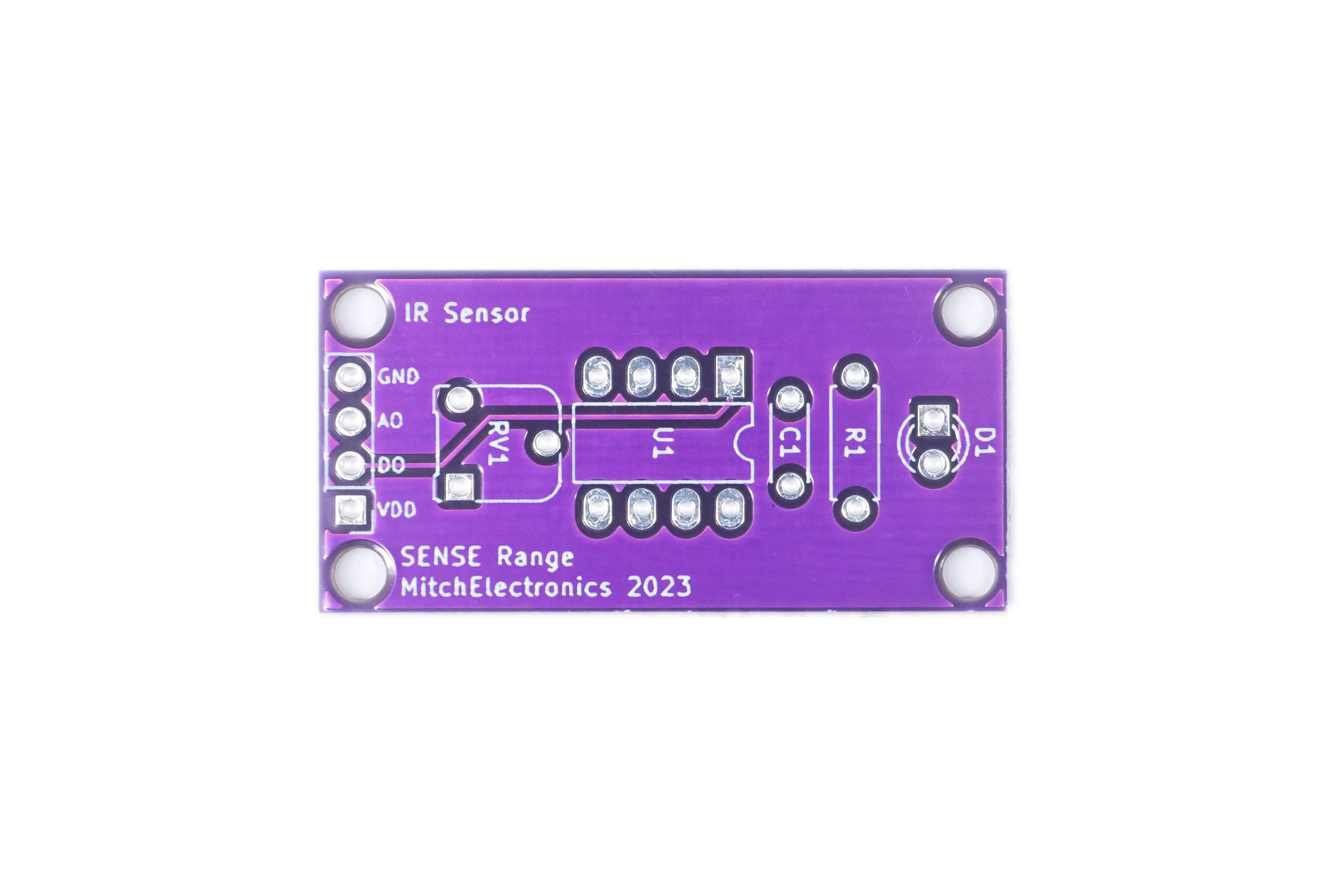
The PCB silkscreen and component references should be checked against the component list before soldering each part.
Before applying power
- Check every component against its PCB reference.
- Confirm the orientation of all polarised components and ICs.
- Inspect for solder bridges, unsoldered pads and clipped leads that could cause a short.
- Check that no loose wire or solder debris remains on the board.
Build with confidence
Construction tips
Recommended build order
A reliable way to assemble IR Sense Kit is to work from the lowest-profile components to the tallest. This keeps the PCB easy to access while you solder.
- Fit resistors, links and other low-profile components first.
- Fit small capacitors and diodes, checking polarity where applicable.
- Fit IC sockets and small semiconductors, observing the orientation markings.
- Fit larger capacitors, potentiometers, switches and other controls.
- Fit LEDs, connectors and the remaining taller components.
- Insert socketed ICs only after soldering around the socket is complete.
- Inspect every joint and check for solder bridges before applying power.
Electronics construction guidance
If you are new to kit construction, use the Soldering Guide alongside these instructions. Identify each component before fitting it and compare its reference with the component list and PCB silkscreen.
When it does not work
Troubleshooting
Nothing happens when power is applied
- Confirm the supply is connected to the correct input and with the correct polarity.
- Check that ICs, diodes, LEDs, transistors and electrolytic capacitors are fitted in the correct orientation.
- Compare component values and positions against the component list and PCB reference.
- Inspect for missed joints, dry joints and accidental solder bridges.
The circuit powers up but does not behave as expected
This kit is intended for infrared signal sensing. If the output is stuck, unstable or outside the expected behaviour, use the schematic to trace the circuit a stage at a time rather than replacing several parts at once.
Check the components around the part of the circuit responsible for the output or timing first. A misplaced resistor, reversed semiconductor or poor connection can allow a circuit to power up while preventing it from operating correctly.
The circuit works intermittently
Intermittent behaviour is often caused by a marginal solder joint, a loose connector or a component lead that has not been fully soldered. Gently inspect the board with power removed and reflow any joint that looks dull, cracked or incomplete.
If the fault remains, compare the assembled board with the schematic and PCB reference one connection at a time.
Ready to test and experiment?
Feeling brave? Consider using different resistors Can be done to change the voltage output of the IR diode
Once the board is working, compare its behaviour with the schematic and the explanation above. Try changing only one input, control or permitted component value at a time so you can clearly see what effect that change has on the circuit.