
Interactive electronics resource
8-Step Tone Sequencer Instructions
Build, understand and experiment with the 8-Step Tone Sequencer. This resource brings the original kit material into the current MitchElectronics format with the schematic, circuit explanation, component and PCB information, construction guidance, troubleshooting and practical ideas where available.
Introduction
The History & Evolution Of Step Sequencers
Step sequencers have a rich history that dates back to the early days of electronic music and synthesizers. Initially developed in the 1960s and 1970s, they became essential tools for creating repeating patterns, rhythms, and melodies in music production. Early sequencers, like those used in classic Moog synthesizers, were primarily analog devices, with a series of steps corresponding to musical notes or actions.
The purpose of a step sequencer is to provide a way to program a sequence of events or notes that repeat at set intervals. This allowed musicians to program rhythmic or melodic loops without having to manually play each note. Over time, these devices evolved from simple, single-purpose machines to more complex tools capable of controlling various musical parameters, such as pitch, rhythm, and timbre.
Step sequencers quickly became a cornerstone in genres such as electronic, techno, and experimental music, where their repetitive nature could be used to create hypnotic and evolving patterns. They also found their place in modular synthesizer setups, where their ability to control multiple parameters in a sequence could lead to intricate and evolving soundscapes.
The benefit of a step sequencer lies in its ability to produce music with a steady, predictable pulse while offering a level of precision that is difficult to achieve through live performance. Furthermore, many modern sequencers come with a wide range of features, from adjustable step lengths and pitch control to randomization and modulation, providing endless possibilities for creative expression.
What is the 8 Step Tone Sequencer Kit?
The 8 Step Tone Sequencer is an analogue musical synthesizer that draws on this rich history of sequencer technology, offering an accessible and hands-on approach to creating funky stepped tones, similar to arpeggios and sequencers. The compact design of the kit, built from multiple MitchElectronics modules, is both practical and educational. It demonstrates how complex electronic circuits can be simplified and integrated into a cohesive system.
By incorporating voltage buffers, such as the 2N7000, this kit introduces new circuit elements that serve as great examples of how analog components can work together to generate rich and complex musical outputs. The 8-step sequencer allows the user to engage in creative music-making by controlling when and how each tone plays, along with adjusting the length of each note and the sequencing rate. Whether for hobbyists, students, or experienced musicians, this kit offers a deep dive into both the technical and artistic aspects of music production.
Schematic
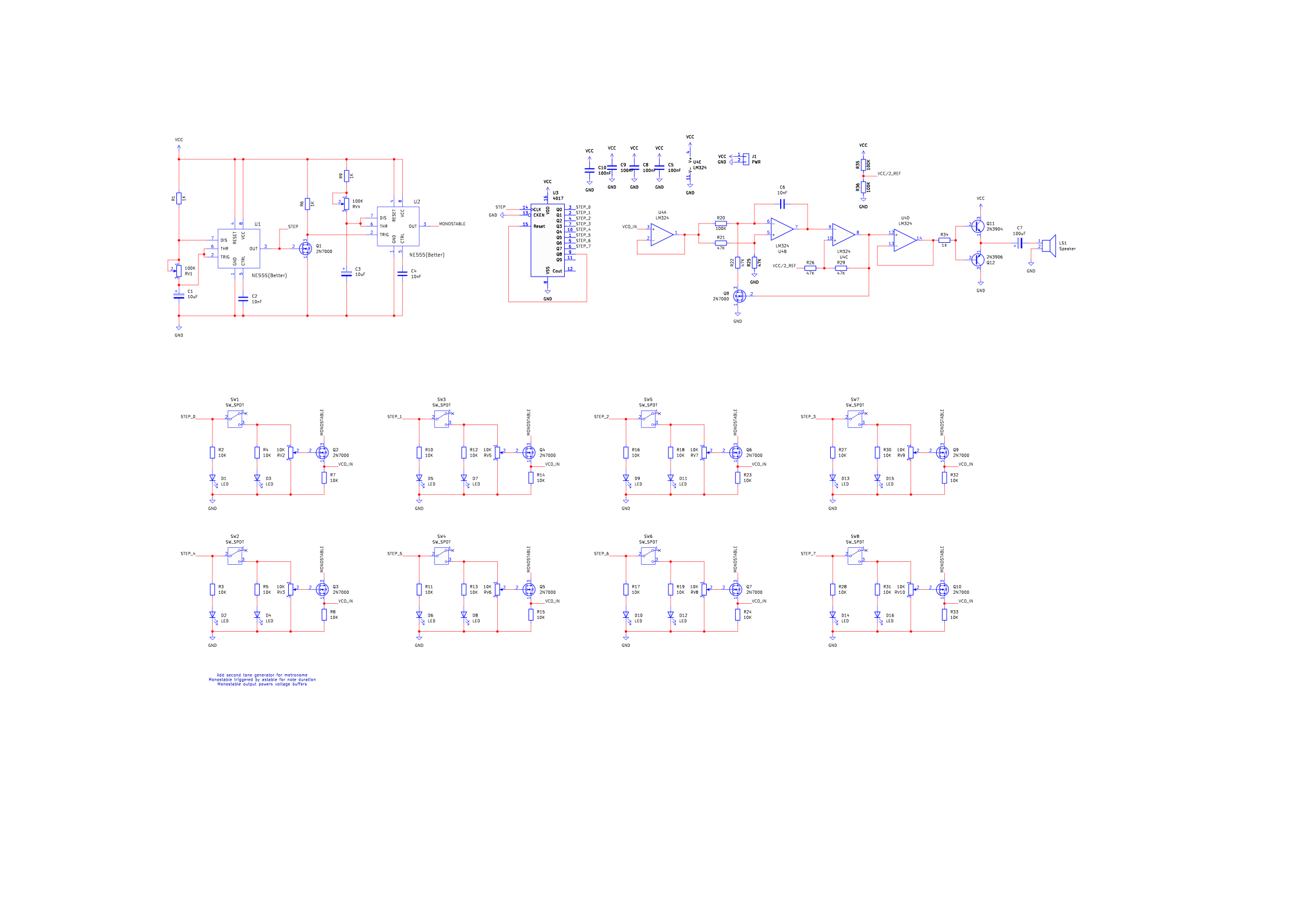
How the 8 step tone sequencer works
The 8-Tone Step Sequencer is a circuit designed to generate a repeating sequence of tones, with each step producing a user-defined pitch and duration. While it may appear complex, it is built using four core circuit elements: a Voltage-Controlled Oscillator (VCO) Kit that generates tones at different frequencies based on input voltage, a 4017 Decade Counter (Johnson Counter) that controls the sequential activation of steps, a 555 Astable Timer that provides the clock signal driving the sequencing process, and a 555 Monostable Timer that defines the duration of each step’s output signal. By integrating these components, the sequencer allows for precise control over pitch, step activation, and duration in a cyclic fashion.
The 555 Astable (Pulse Generator)
The 555 astable multivibrator generates a continuous clock signal that acts as the heartbeat of the sequencer and determines the speed at which the steps progress. The output of this 555 astable circuit oscillates between high (5V) and low (0V), creating a square wave signal. This clock signal is fed into the clock input (pin 14) of the 4017 decade counter, causing it to increment its output with each pulse. The oscillation frequency of the 555 astable determines how quickly the sequencer steps through its cycle.
The 4017 Counter (Step Sequencer)
The 4017 counter is a Johnson decade counter that sequentially activates one of its ten outputs (Q0–Q9) with each clock pulse. Since the sequencer requires only eight steps, the ninth step (Q8) is connected to the reset pin (pin 15), causing it to loop back to the first step. Initially, Q0 (first step) is high while all other outputs remain low. Each clock pulse from the 555 astable shifts the high output to the next step. After reaching Q7 (eighth step), the next pulse triggers the reset, returning the sequence to Q0. This creates a continuous cycle of eight sequential outputs.
Tone Step (Enable / Voltage Generation)
Each of the eight outputs from the 4017 counter is connected to an individual step circuit that determines whether a tone is played and at what frequency. Each step circuit consists of a red LED that indicates the currently active step, a switch that allows the user to enable or disable the step, a green LED that lights up when a tone is being produced, a potentiometer that adjusts the voltage controlling the VCO frequency, and a 2N7000 NMOS transistor functioning as a voltage follower to buffer the voltage output. When a step is active, the corresponding red LED lights up, showing which step is currently selected. The user can control whether the step is enabled using a switch. If the switch is turned on, the step’s voltage is processed and used to generate a tone; if turned off, the step is skipped, and no tone is played. If a step is active and enabled, the green LED will light up, signaling that the VCO is receiving a control voltage. The 4017 output voltage (5V) is fed into a potentiometer, allowing the user to adjust the voltage between 0V and 5V. This voltage directly determines the pitch of the VCO-generated tone.
Tone Step (Output Buffer / Length Control)
Each step output is fed through a 2N7000 NMOS transistor, which is configured as a voltage follower (source follower). This serves two essential functions. First, it buffers the signal to ensure that each step’s output voltage is not affected by the load of the VCO input. Second, it isolates the steps, preventing the potentiometers from interacting with each other, which would otherwise lead to interference in the tone generation.
The 555 Monostable (Length Control)
While the 4017 counter determines when each step is activated, the 555 monostable timer controls how long the tone is played for each step. When a step is triggered, the monostable 555 timer generates a pulse of a specific width. This pulse controls the gate of the NMOS transistor buffer, allowing the corresponding step’s voltage to reach the VCO only for a set duration. The pulse width is determined by the RC timing components of the monostable 555 timer and can be adjusted to control the length of each note.
VCO (Tone Generation)
All buffered step outputs feed into a single VCO input, meaning that at any given time, only the currently active step’s voltage is sent to the VCO. The VCO generates a tone at a frequency corresponding to this voltage, producing the final output sound. The overall process consists of the 555 astable clock advancing the 4017 counter through its steps, each step circuit determining whether a tone should be played and at what pitch, the 555 monostable timer controlling how long each tone lasts, and buffered step voltages being sent to the VCO, generating the final sound output. This results in an eight-step repeating sequence of tones, with user-defined control over which steps play, what pitch they produce, and how long they last.
Project ideas
Lo-Fi Melody Generator
Use the sequencer to create a repeating melody that can be integrated into a lo-fi or ambient music setup. By connecting it to a synth or external sound module, you can generate hypnotic, evolving patterns that add texture to your music.
Drum Machine
Modify the sequencer to trigger drum sounds instead of tones. Each step can activate a different percussive element, such as a kick, snare, hi-hat, or clap. With some additional circuitry, it can function as a basic analog drum sequencer.
Interactive Sound Installation
Combine the sequencer with sensors (such as light sensors or touch pads) to create an interactive experience. When someone moves near the installation, the sequence changes in speed or pitch, making it a reactive sound artwork.
Randomized Ambient Soundscape
Incorporate randomization by using a noise generator or a chaotic oscillator to slightly vary each step’s voltage. This would create evolving, non-repeating patterns that could be used for ambient or generative music.
MIDI-Controlled Sequencer
Modify the sequencer to output MIDI signals instead of analog voltages. This would allow you to control software synthesizers, digital audio workstations (DAWs), or MIDI-compatible hardware for a hybrid analog-digital setup.
Laser Light Show Synchronization
Sync the sequencer with a set of laser diodes or LED strips. Each step could trigger a different light pattern or color, turning the sequencer into a basic audiovisual performance tool.
Robot Noisemaker
Attach small motors or servos to the sequencer outputs so that each step activates a moving part of a simple robotic instrument. This could be used to create mechanical beats or rhythmic noise effects.
Circuit-Bent Experimental Synth
Modify the circuit by adding bend points, glitch switches, or feedback loops to introduce unpredictable, noisy, and glitchy sound effects. This could be a great way to explore experimental sound design.
Step-Controlled Radio Synth
Hack an old AM/FM radio and use the sequencer to control the tuning voltage. Each step could shift the frequency slightly, generating eerie, evolving radio noise textures.
Analog Algorithmic Composer
Combine multiple sequencers, each running at different speeds, to create algorithmic compositions. By overlapping different sequences, you can create polyrhythms and complex evolving melodies.
Try it yourself
Circuit simulation
What you need
Component List
Inspect the board
Interactive BOM
Board reference
PCB & assembly
The PCB silkscreen and component references should be checked against the component list before soldering each part.
Before applying power
- Check every component against its PCB reference.
- Confirm the orientation of all polarised components and ICs.
- Inspect for solder bridges, unsoldered pads and clipped leads that could cause a short.
- Check that no loose wire or solder debris remains on the board.
Build with confidence
Construction tips
Recommended build order
A reliable way to assemble 8-Step Tone Sequencer is to work from the lowest-profile components to the tallest. This keeps the PCB easy to access while you solder.
- Fit resistors, links and other low-profile components first.
- Fit small capacitors and diodes, checking polarity where applicable.
- Fit IC sockets and small semiconductors, observing the orientation markings.
- Fit larger capacitors, potentiometers, switches and other controls.
- Fit LEDs, connectors and the remaining taller components.
- Insert socketed ICs only after soldering around the socket is complete.
- Inspect every joint and check for solder bridges before applying power.
Electronics construction guidance
If you are new to kit construction, use the Soldering Guide alongside these instructions. Identify each component before fitting it and compare its reference with the component list and PCB silkscreen.
When it does not work
Troubleshooting
Nothing happens when power is applied
- Confirm the supply is connected to the correct input and with the correct polarity.
- Check that ICs, diodes, LEDs, transistors and electrolytic capacitors are fitted in the correct orientation.
- Compare component values and positions against the component list and PCB reference.
- Inspect for missed joints, dry joints and accidental solder bridges.
The circuit powers up but does not behave as expected
This kit is intended for eight-step analogue tone sequencer. If the output is stuck, unstable or outside the expected behaviour, use the schematic to trace the circuit a stage at a time rather than replacing several parts at once.
Check the components around the part of the circuit responsible for the output or timing first. A misplaced resistor, reversed semiconductor or poor connection can allow a circuit to power up while preventing it from operating correctly.
The circuit works intermittently
Intermittent behaviour is often caused by a marginal solder joint, a loose connector or a component lead that has not been fully soldered. Gently inspect the board with power removed and reflow any joint that looks dull, cracked or incomplete.
If the fault remains, compare the assembled board with the schematic and PCB reference one connection at a time.
Ready to test and experiment?
Once the board is working, compare its behaviour with the schematic and the explanation above. Try changing only one input, control or permitted component value at a time so you can clearly see what effect that change has on the circuit.