
Interactive electronics resource
555 Synth Punk Kit Instructions
Build, understand and experiment with the 555 Synth Punk Kit. This resource brings the original kit material into the current MitchElectronics format with the schematic, circuit explanation, component and PCB information, construction guidance, troubleshooting and practical ideas where available.
Introduction
What is the 555 timer IC?
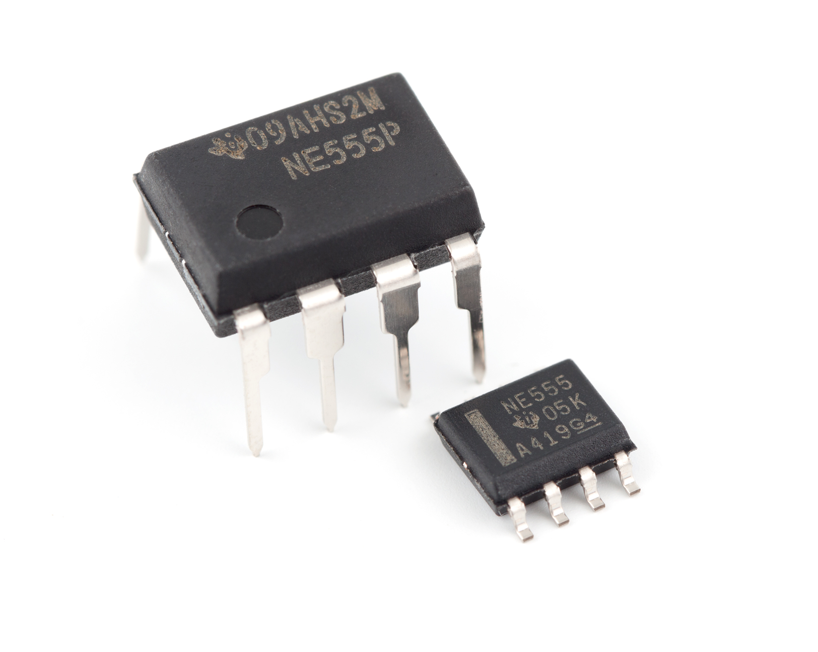
The 555 timer IC is arguably one of the most famous integrated circuits that have ever been manufactured. The 555 is such a popular chip that despite having been invented in 1972 it is still produced in the millions each year to this day.
Ever since the first 555 timer, many variations have been designed such as the 556 which includes two 555 timers on the same chip, CMOS versions that use less power, and SMD varieties that allow the 555 to be used on the smallest PCBs.
How is the 555 timer IC used?
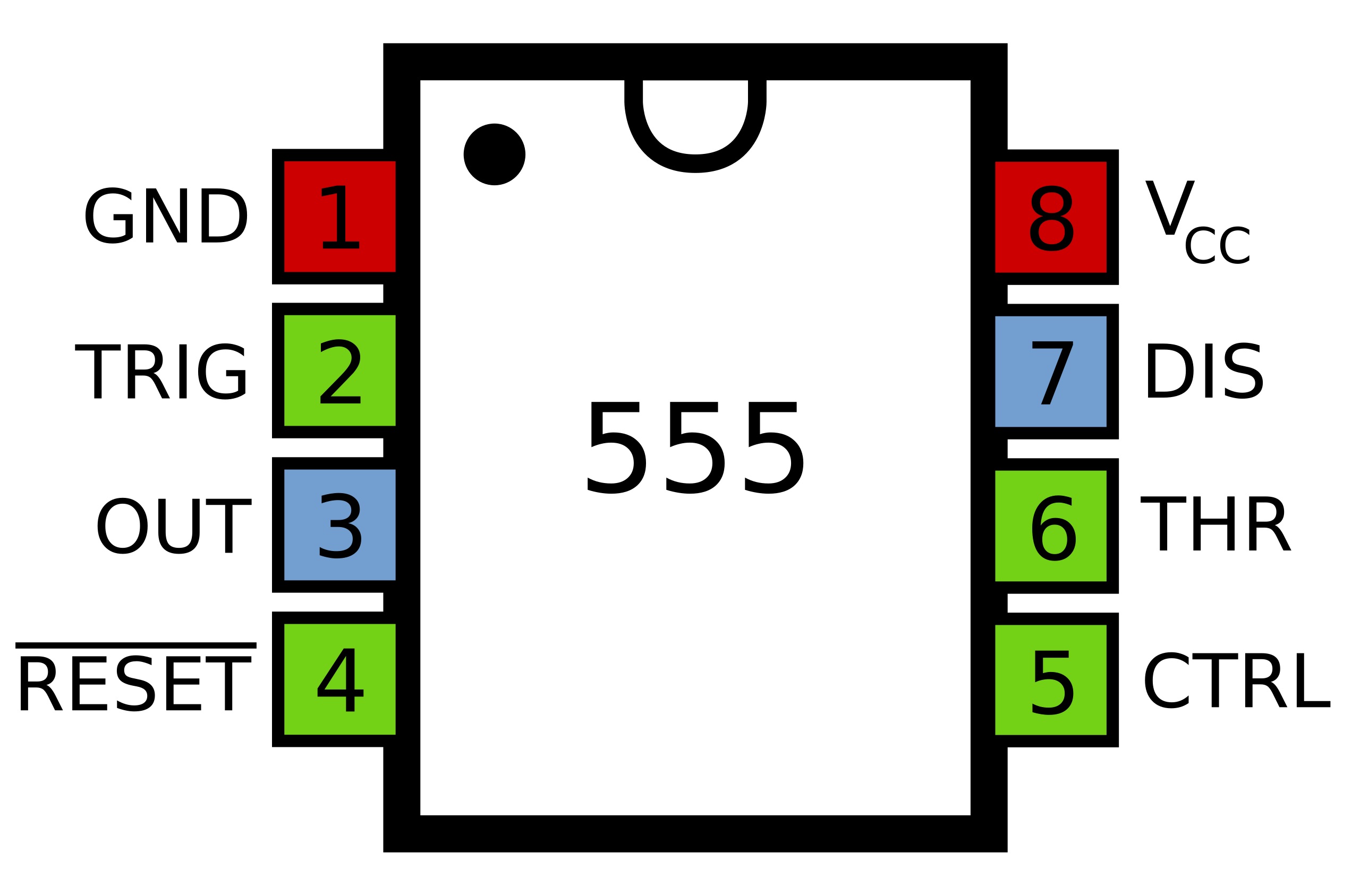
As the name suggests, the 555 timer is primarily designed as a timer IC which can be used to either produce a constant square wave (astable mode), or a one-shot square signal (monostable mode).
However, the 555 can also be used to do many other things, such as a digital modulator, a latch, and a PWM generator. All of these functions can be realised with the use of external components and clever circuit routing.
Where can you find the 555 timer?
The 555 timer used to be a staple in many circuits, but its used in modern electronics is not as obvious. Many low-cost electronics devices from the far-east will often use them (such as relay controls and timers).
The popularity of the 555 timer in the past also sees it in older electronic systems that are still in use. If these circuits fail, a new 555 can replace it!
Schematic
How does the 555 synth punk work?
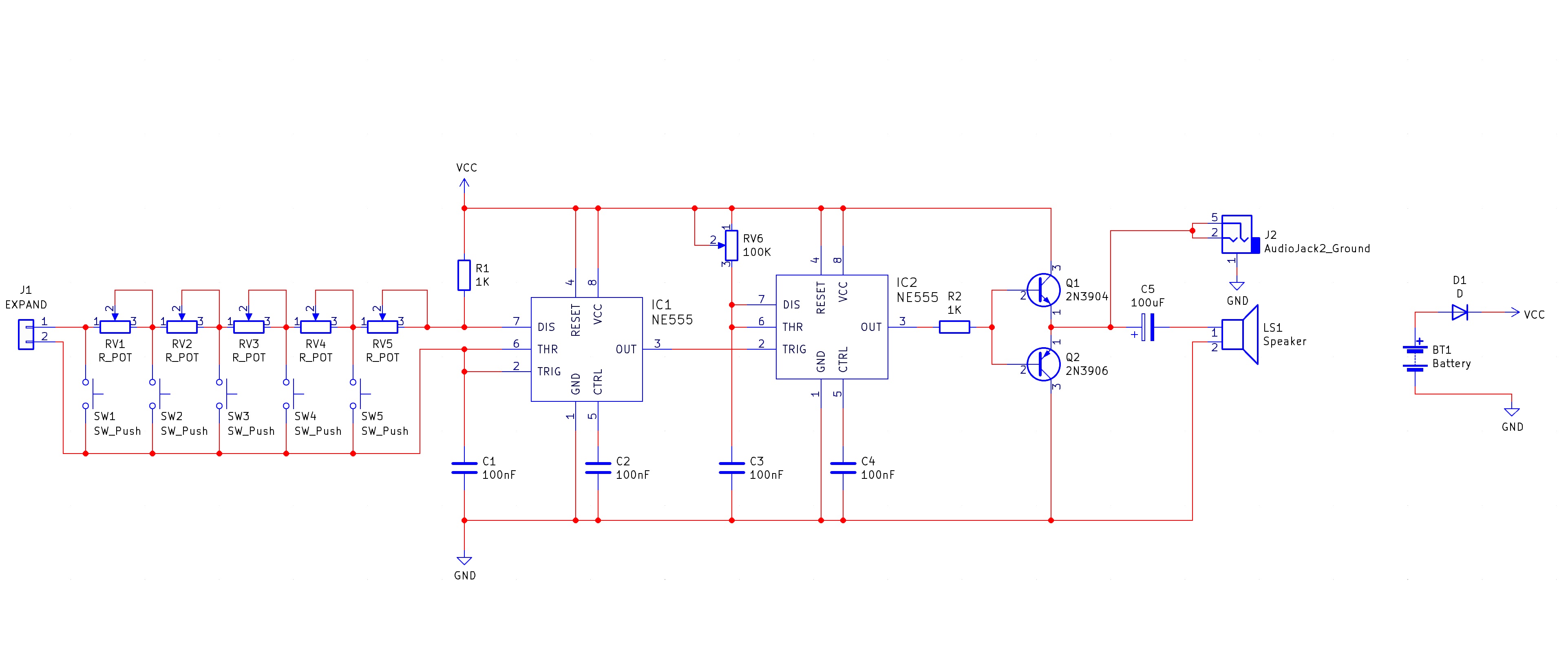
The 555 Synth Punk Kit is arguably one of the hardest kits to explain how it works. One of the reasons for this complexity is that it includes some music theory, an astable, and a monostable circuit which all work in a very specific way to produce some rather wacky tones.
To start, the 555 Synth Punk is made up of the following sub-circuits
Tone Keys – These are the keys that you press to produce a tone 555 Astable Oscillator – This produces a square wave signal 555 Monostable – This is a triggerable monostable that produces the output audio wave Output stage – This converts the weak 555 signal into one that can drive a speaker
The first stage is the tone keys which are the same as those on a keyboard; each one produces a different tone. If you look at the schematic carefully you will see that these buttons are in series with potentiometers. When a key is pressed, the voltage signal from pin 7 on the 555 IC2 has to go through all the potentiometers up to the pressed switch, whereby it can return back to the 555s pin 6. The result is that switch 5 has the least resistance while switch 1 has the most resistance, and therefore pressing switch 5 will produce the highest output frequency while pressing switch 1 will produce the lowest frequency.
The second stage is where the magic behind the 555 Synth Punk happens. If a speaker was connected to the output of the 555 astable you would have a simple circuit which would produce different tones depending on the switch that you pressed. However, in the Synth Punk circuit, the 555 astable is triggering a 555 monostable whose “on” time is tuneable with a potentiometer. If a button is held and the potentiometer is adjusted from one extreme to the other you will hear a stepped pattern. Why does this happen?
The reason for this is that the 555 monostable is NOT a re-triggerable monostable. When the monostable is triggered its output turns on for a set amount of time. During this time, if the TRIG pin is re-triggered the monostable does not restart itself but instead ignores it. If the potentiometer is left at a specific position, then a specific output frequency will be produced, which relates the input trigger frequency to the output of the monostable. If the potentiometer is adjusted so that the length of the output of the 555 monostable is increased and crosses a pulse from the 555 astable then suddenly, the output of the 555 monostable will drop significantly as the pulse that was crossed is no longer able to trigger the 555 monostable and therefore reduces the frequency. This is a very hard concept to explain and is best seen with an oscilloscope or on a video.
The final stage is a push-pull amplifier that improves the output impedance of the 555 monostable so that a speaker can be properly driven. The circuit also has a 3.5mm phono output so that an external speaker can be connected to the 555 Synth Punk for live audiences!
Project ideas
Basic Synthesiser
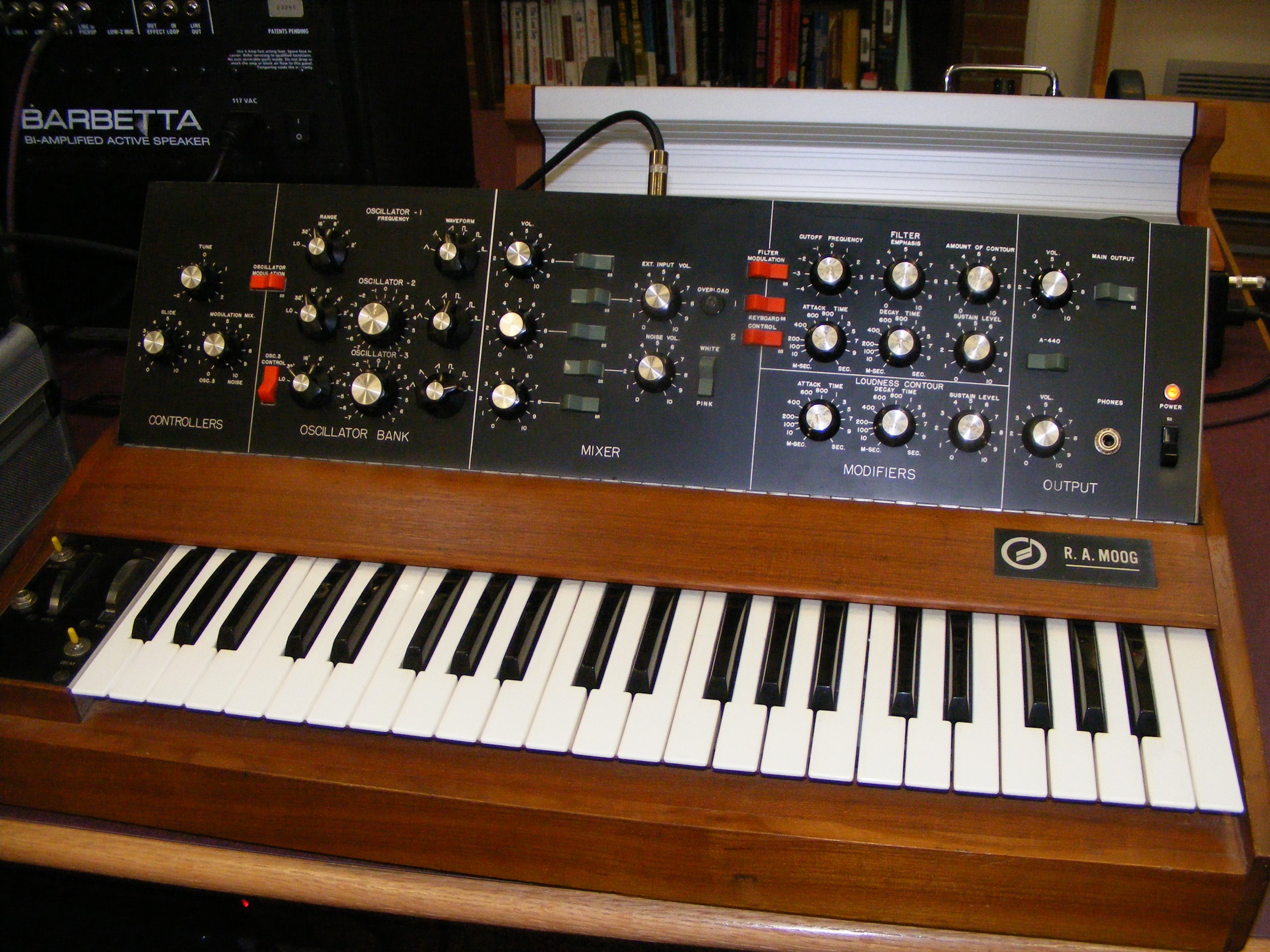
The most obvious use for the 555 Synth Punk is as a synthesiser. In fact, this kit is ideal for those wanting to give live performances, as the various controls allow for changes in the sound output, and this can be exploited to make unique sounds at the time of performance.
If integrated into an enclosure, the kit can be easier to interface with, and larger external buttons could be used to provide more responsive operation (i.e. easier to push a large soft button than a smaller tactile switch).
Try it yourself
Circuit simulation
Not available in mobile view
What you need
Component List
| Component | Quantity | PCB Reference |
|---|---|---|
| 8 DIP Socket | 2 | IC1, IC2 |
| NE555 | 2 | IC1, IC2 |
| 100nF Capacitor | 4 | C1, C2, C3, C4 |
| 100uF Capacitor | 1 | C5 |
| 1KΩ Resistor | 2 | R1, R2 |
| 10KΩ Potentiometer | 5 | RV1 to RV5 |
| 100KΩ Potentiometer | 1 | RV6 |
| 1N5817 Diode | 1 | D1 |
| 2N3904 | 1 | Q1 |
| 2N3906 | 1 | Q2 |
| Speaker | 1 | LS1 |
| Tactile Switch | 5 | SW1 to SW5 |
| 3.5mm Phono Socket | 1 | 2 |
| Black Wire | 1 | LS1 - |
| Red Wire | 1 | LS1 + |
| PP3 Connector | 1 | BT1 |
| 555 Synth Punk PCB | 1 | — |
Inspect the board
Interactive BOM
Board reference
PCB & assembly
The PCB silkscreen and component references should be checked against the component list before soldering each part.
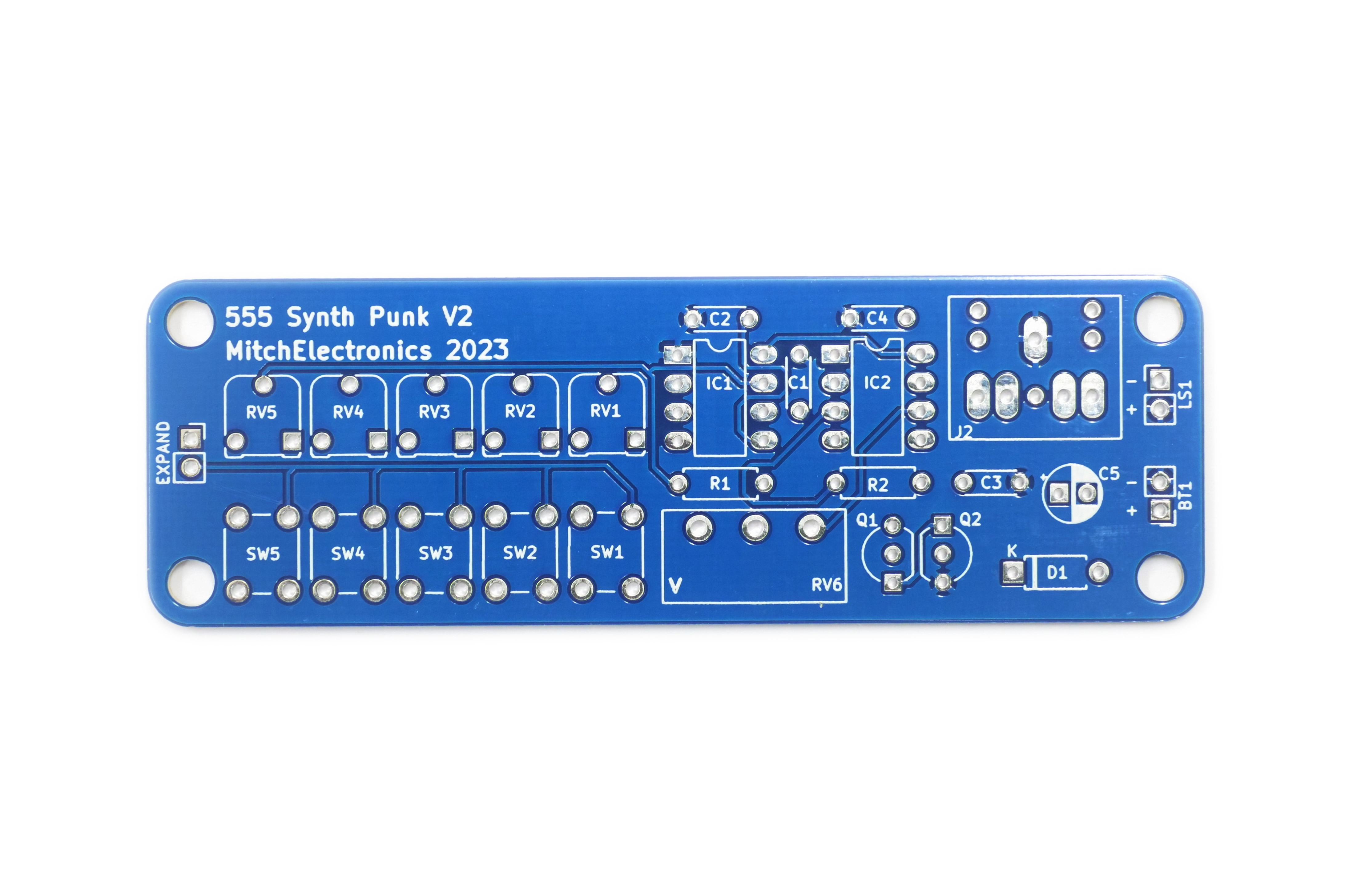
Before applying power
- Check every component against its PCB reference.
- Confirm the orientation of all polarised components and ICs.
- Inspect for solder bridges, unsoldered pads and clipped leads that could cause a short.
- Check that no loose wire or solder debris remains on the board.
Build with confidence
Construction tips
Recommended build order
A reliable way to assemble 555 Synth Punk Kit is to work from the lowest-profile components to the tallest. This keeps the PCB easy to access while you solder.
- Fit resistors, links and other low-profile components first.
- Fit small capacitors and diodes, checking polarity where applicable.
- Fit IC sockets and small semiconductors, observing the orientation markings.
- Fit larger capacitors, potentiometers, switches and other controls.
- Fit LEDs, connectors and the remaining taller components.
- Insert socketed ICs only after soldering around the socket is complete.
- Inspect every joint and check for solder bridges before applying power.
Electronics construction guidance
If you are new to kit construction, use the Soldering Guide alongside these instructions. Identify each component before fitting it and compare its reference with the component list and PCB silkscreen.
When it does not work
Troubleshooting
Nothing happens when power is applied
- Confirm the supply is connected to the correct input and with the correct polarity.
- Check that ICs, diodes, LEDs, transistors and electrolytic capacitors are fitted in the correct orientation.
- Compare component values and positions against the component list and PCB reference.
- Inspect for missed joints, dry joints and accidental solder bridges.
The circuit powers up but does not behave as expected
This kit is intended for 555-based experimental sound generator. If the output is stuck, unstable or outside the expected behaviour, use the schematic to trace the circuit a stage at a time rather than replacing several parts at once.
Check the components around the part of the circuit responsible for the output or timing first. A misplaced resistor, reversed semiconductor or poor connection can allow a circuit to power up while preventing it from operating correctly.
The circuit works intermittently
Intermittent behaviour is often caused by a marginal solder joint, a loose connector or a component lead that has not been fully soldered. Gently inspect the board with power removed and reflow any joint that looks dull, cracked or incomplete.
If the fault remains, compare the assembled board with the schematic and PCB reference one connection at a time.
Ready to test and experiment?
Feeling brave? Consider using different resistors and capacitors Can be done to create different tones and sounds Use an external potentiometer on the EXPAND port for additional tone changes
Once the board is working, compare its behaviour with the schematic and the explanation above. Try changing only one input, control or permitted component value at a time so you can clearly see what effect that change has on the circuit.