
Interactive electronics resource
4516 Binary Counter Instructions
Build, understand and experiment with the 4516 Binary Counter. This resource brings the original kit material into the current MitchElectronics format with the schematic, circuit explanation, component and PCB information, construction guidance, troubleshooting and practical ideas where available.
Introduction
Pre-learning – The Logic Gate Board
Before you learn how the 4516 Binary Counter Board works, you should first learn how the Logic Gate Board works as that kit covers the basics of logic. The Logic Gate Board kit also provides multiple logic chips in the 4000 series, demonstrating how these chips work and how some of the 4000 series share similar packages and configurations.
Schematic
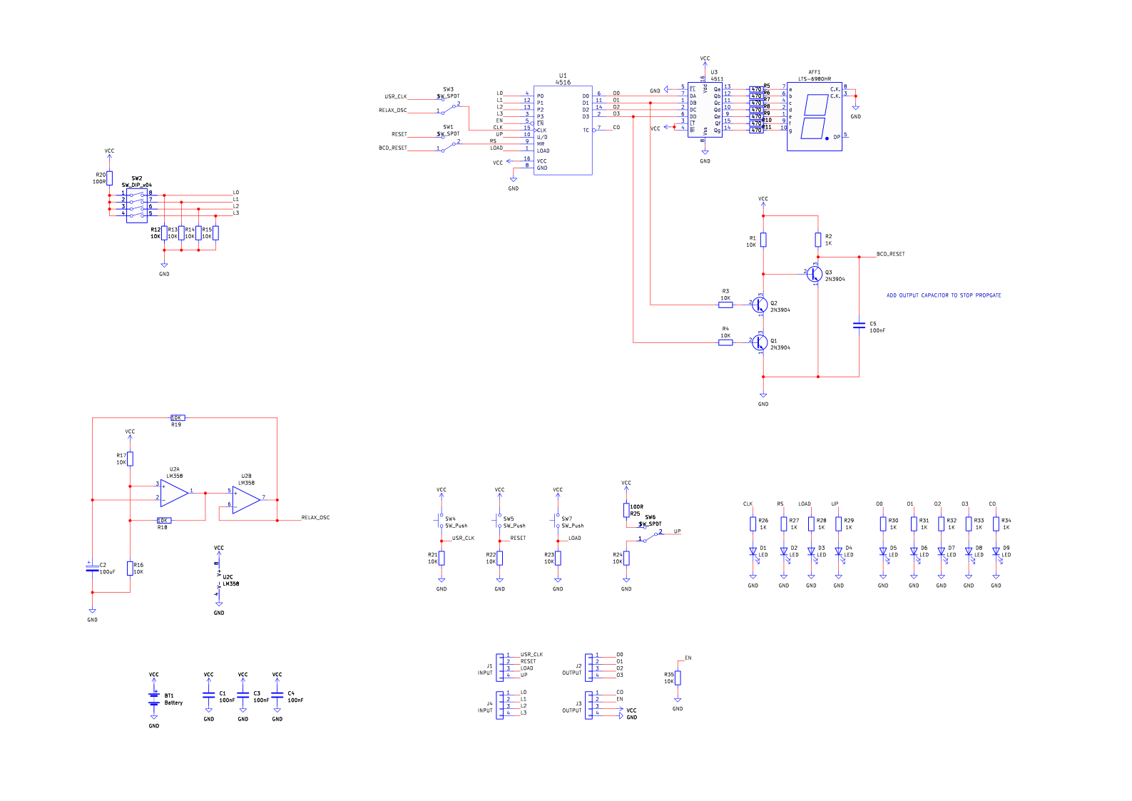
How does the 4516 counter board work?
The 4516 Binary Counter kit is a circuit that shows you how the 4516 Binary Up/Down counter works, integrating a counter, debounce circuit, and even a BCD reset (more on this later).
At the heart of this kit is the 4516 4-bit binary counter, which is a part of the 4000 series of logic chips, manufactured by numerous companies (TI, RCA, HGSEMI, etc.), and is extremely popular in discrete logic circuits. Like typical counters, this chip has a 4-bit output representing the current count, a clock input, reset input, and direction input.
However, the 4516 also integrates a 4-bit input and load pin which allows for the counter to be present to a specific value. This can be extremely handy if needing to change the output to some arbitrary number, and can be thought of presetting a countdown kitchen timer.
In addition to the 4516, the kit also integrates the 4585 7-SEG BCD decoder chip, which takes in binary numbers and converts them to a decimal number that can be shown on a 7 segment display. However, because the chip can only drive one display, numbers greater than 9 are shown as a blank screen. This IC will not be looked at in detail in this kit, but will be in future kits.
The clock input to the 4516 is selectable (via SW3) between a push button and a relaxation oscillator, which allows for either manual clocking, or having the 4516 automatically count up and down. With regards to the count direction, a small slide switch (SW6) allows for setting the direction.
To demonstrate counting in binary vs. counting in decimal, an additional switch (SW1) has been provided which allows for resetting the 4516 either by the reset button (SW5) or a secondary glue logic circuit (Q1 and Q2). The glue logic will reset the 4516 when it reaches the value of 10, making the counter count from 0 to 9. However, this only works when incrementing, and will not work when decrementing.
Try it yourself
Circuit simulation
What you need
Component List
| Component | Quantity | PCB Reference |
|---|---|---|
| 16 DIP Sockets | 2 | U1, U3 |
| 8 DIP Socket | 1 | U2 |
| 4516 IC | 1 | U1 |
| 4511 IC | 1 | U3 |
| LM358 | 1 | U2 |
| 100nF Capacitor | 4 | C1, C3, C4, C5 |
| 100uF Capacitor | 1 | C2 |
| 100R Resistor | 2 | R20, R25 |
| 470R Resistors | 7 | R5, R6, R7, R8, R9, R10, R11 |
| 10K Resistors | 10 | R1, R3, R4, R12, R13, R14, R15, R16, R17, R18, R19, R21, R22, R23, R24, R35 |
| 2N3904 Transistors | 3 | Q1, Q2, Q3 |
| Red LEDs | 9 | D1, D2, D3, D4, D5, D6, D7, D8, D9 |
| 7 Segment Display | 1 | AFF1 |
| Tactile Switches | 3 | SW4, SW5, SW7 |
| Mini Slide Switches | 3 | SW1, SW3, SW6 |
| 4-Way DIP Switch | 1 | SW2 |
| PP3 Connector | 1 | BT1 |
| 4516 Binary Counter PCB | 1 | — |
Inspect the board
Interactive BOM
Board reference
PCB & assembly
The PCB silkscreen and component references should be checked against the component list before soldering each part.
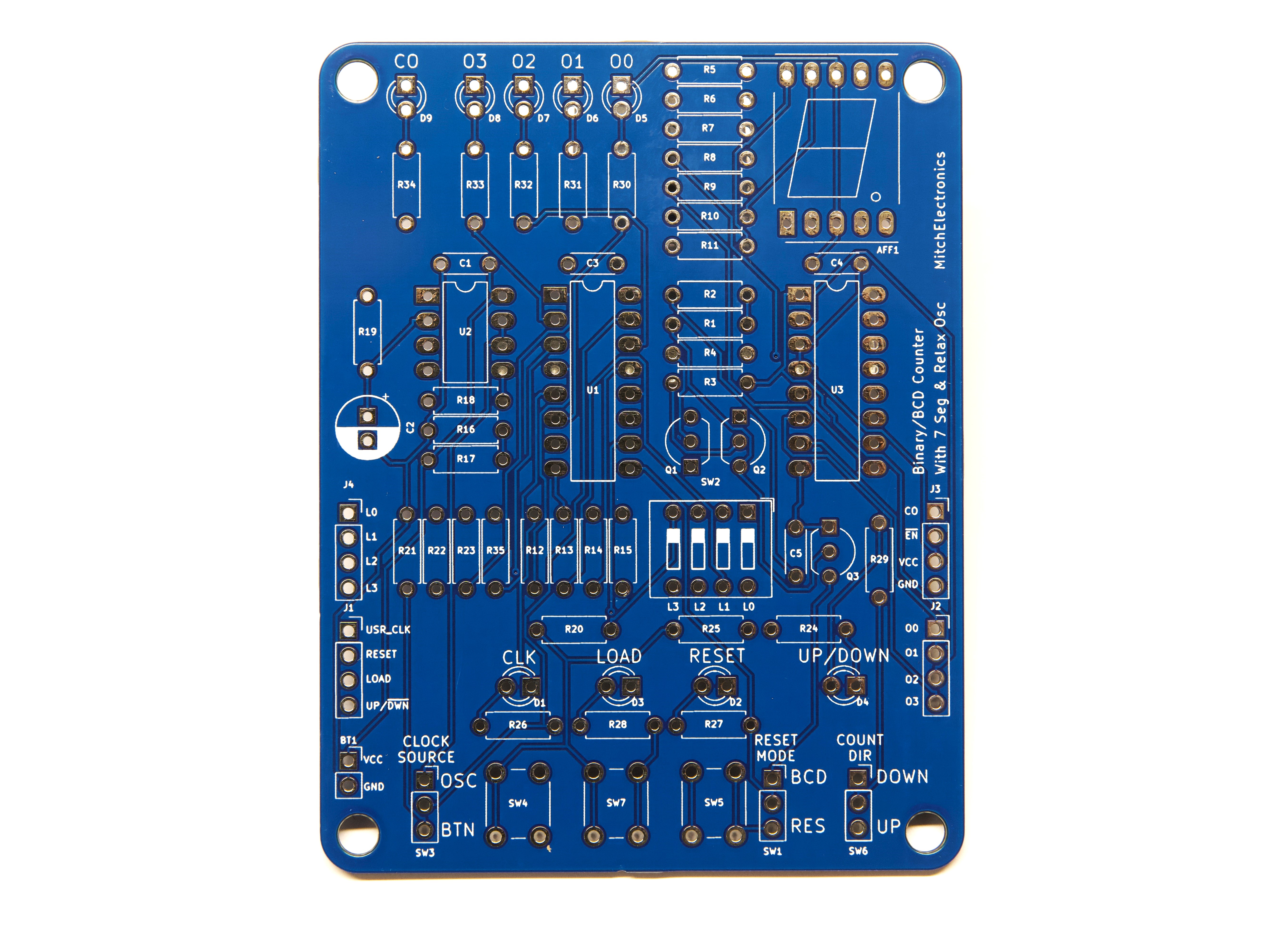
Before applying power
- Check every component against its PCB reference.
- Confirm the orientation of all polarised components and ICs.
- Inspect for solder bridges, unsoldered pads and clipped leads that could cause a short.
- Check that no loose wire or solder debris remains on the board.
Build with confidence
Construction tips
Recommended build order
A reliable way to assemble 4516 Binary Counter is to work from the lowest-profile components to the tallest. This keeps the PCB easy to access while you solder.
- Fit resistors, links and other low-profile components first.
- Fit small capacitors and diodes, checking polarity where applicable.
- Fit IC sockets and small semiconductors, observing the orientation markings.
- Fit larger capacitors, potentiometers, switches and other controls.
- Fit LEDs, connectors and the remaining taller components.
- Insert socketed ICs only after soldering around the socket is complete.
- Inspect every joint and check for solder bridges before applying power.
Electronics construction guidance
If you are new to kit construction, use the Soldering Guide alongside these instructions. Identify each component before fitting it and compare its reference with the component list and PCB silkscreen.
When it does not work
Troubleshooting
Nothing happens when power is applied
- Confirm the supply is connected to the correct input and with the correct polarity.
- Check that ICs, diodes, LEDs, transistors and electrolytic capacitors are fitted in the correct orientation.
- Compare component values and positions against the component list and PCB reference.
- Inspect for missed joints, dry joints and accidental solder bridges.
The circuit powers up but does not behave as expected
This kit is intended for presettable binary counter experimentation. If the output is stuck, unstable or outside the expected behaviour, use the schematic to trace the circuit a stage at a time rather than replacing several parts at once.
Check the components around the part of the circuit responsible for the output or timing first. A misplaced resistor, reversed semiconductor or poor connection can allow a circuit to power up while preventing it from operating correctly.
The circuit works intermittently
Intermittent behaviour is often caused by a marginal solder joint, a loose connector or a component lead that has not been fully soldered. Gently inspect the board with power removed and reflow any joint that looks dull, cracked or incomplete.
If the fault remains, compare the assembled board with the schematic and PCB reference one connection at a time.
Ready to test and experiment?
Use a signal generator to test how fast the logic circuits can respond to signals
Once the board is working, compare its behaviour with the schematic and the explanation above. Try changing only one input, control or permitted component value at a time so you can clearly see what effect that change has on the circuit.