
Interactive electronics resource
4017 Light Chaser Kit Instructions
Build, understand and experiment with the 4017 Light Chaser Kit. This resource brings the original kit material into the current MitchElectronics format with the schematic, circuit explanation, component and PCB information, construction guidance, troubleshooting and practical ideas where available.
Introduction
The 4017 Light Chaser Kit is a hands-on electronics project designed around a sequential led light chaser. Use the schematic and component references in this guide to understand the circuit as you assemble and test it.
Schematic
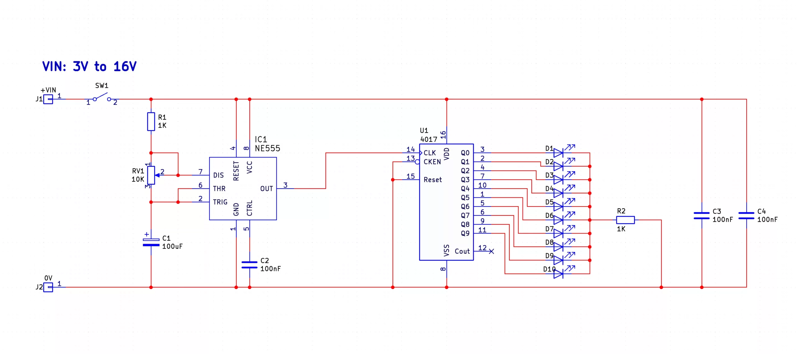
How does the 4017 light chaser work?
The 4017 light chaser is made up of two main circuits; a 555 astable oscillator and a 4017 5-stage Johnson counter. The 555 astable circuit is made up of a single 555 timer, a potentiometer (RV1), a resistor (R1), and a capacitor (C1). This circuit outputs a square wave whose frequency is determined by the resistance of RV1 and the larger the resistance of RV1 the slower the output frequency. You can learn more about the 555 astable circuit with this kit available from MitchElectronics. The output of the 555 astable is connected to the clock input of the 4017 and every time the output of the 555 transitions from low to high the 4017 counter transitions to the next state. The 4017 has 10 outputs that each turn on after the previous output has been turned off. The best way to see this is to look at the table below which shows the output states for each clock pulse that is fed into the CLK pin.
Each one of the outputs of the 4017 is connected to an LED and all the LEDs are connected to a single resistor, R2, in series with ground. LEDs in parallel typically require a series resistor for each LED but in this case, the circuit only requires one resistor as only one LED will ever be on and therefore, the brightness of each LED will be the same. The 4017 also has two other inputs that are not used in this circuit but may be useful to learn about; CLKEN and RESET. The CLKEN pin is an active low pin and when this pin is low (i.e. 0V), the 4017 counter will count every time a clock pulse is detected. If this pin is connected to high (i.e. +V) then the counter will not count when a clock pulse is detected and can be useful for enabling/disabling the counter. The RESET pin is an active high pin and when connected to high (i.e. +V), the counter will reset all outputs. This is useful for setting the counter to a known state (output Q0 = 1).
Try it yourself
Circuit simulation
Not available in mobile view
What you need
Component List
| Component | Quantity | PCB Reference |
|---|---|---|
| 16 DIP Socket | 1 | U1 |
| 8 DIP Socket | 1 | IC1 |
| 4017 | 1 | U1 |
| 555 | 1 | IC1 |
| 1K Resistors | 2 | R1, R2 |
| 100nF Capacitors | 3 | C2, C3, C4 |
| 100uF Capacitor | 1 | C1 |
| 10K Potentiometer | 1 | RV1 |
| Small Slide Switch | 1 | SW1 |
| Red LED | 10 | D1, D2, D3, D4, D5, D6, D7, D8, D9, D10 |
| PP3 Connector | 1 | VIN, 0V |
| 4017 Light Chaser PCB | 1 | — |
Inspect the board
Interactive BOM
Board reference
PCB & assembly
The PCB silkscreen and component references should be checked against the component list before soldering each part.
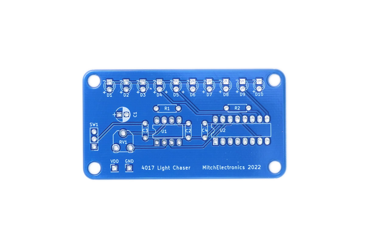
Before applying power
- Check every component against its PCB reference.
- Confirm the orientation of all polarised components and ICs.
- Inspect for solder bridges, unsoldered pads and clipped leads that could cause a short.
- Check that no loose wire or solder debris remains on the board.
Build with confidence
Construction tips
Recommended build order
A reliable way to assemble 4017 Light Chaser Kit is to work from the lowest-profile components to the tallest. This keeps the PCB easy to access while you solder.
- Fit resistors, links and other low-profile components first.
- Fit small capacitors and diodes, checking polarity where applicable.
- Fit IC sockets and small semiconductors, observing the orientation markings.
- Fit larger capacitors, potentiometers, switches and other controls.
- Fit LEDs, connectors and the remaining taller components.
- Insert socketed ICs only after soldering around the socket is complete.
- Inspect every joint and check for solder bridges before applying power.
Electronics construction guidance
If you are new to kit construction, use the Soldering Guide alongside these instructions. Identify each component before fitting it and compare its reference with the component list and PCB silkscreen.
When it does not work
Troubleshooting
Nothing happens when power is applied
- Confirm the supply is connected to the correct input and with the correct polarity.
- Check that ICs, diodes, LEDs, transistors and electrolytic capacitors are fitted in the correct orientation.
- Compare component values and positions against the component list and PCB reference.
- Inspect for missed joints, dry joints and accidental solder bridges.
The circuit powers up but does not behave as expected
This kit is intended for sequential led light chaser. If the output is stuck, unstable or outside the expected behaviour, use the schematic to trace the circuit a stage at a time rather than replacing several parts at once.
Check the components around the part of the circuit responsible for the output or timing first. A misplaced resistor, reversed semiconductor or poor connection can allow a circuit to power up while preventing it from operating correctly.
The circuit works intermittently
Intermittent behaviour is often caused by a marginal solder joint, a loose connector or a component lead that has not been fully soldered. Gently inspect the board with power removed and reflow any joint that looks dull, cracked or incomplete.
If the fault remains, compare the assembled board with the schematic and PCB reference one connection at a time.
Ready to test and experiment?
Feeling brave? Hack the PCB and connect multiple 4017 kits together to make even longer chains!
Once the board is working, compare its behaviour with the schematic and the explanation above. Try changing only one input, control or permitted component value at a time so you can clearly see what effect that change has on the circuit.